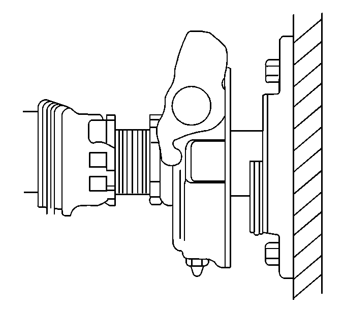
Clutch Assembly Adjustment 13 Inch Valeo Cable
- Apply the parking brake.
- Remove the return spring from the side of the transmission.
- Loosen the jam and adjusting nuts and position both nuts away from the spacer block.
- Pull rearward on the clutch lever (Fork). Apply about seven pounds of force toward the engaged position (Rearward).
- Apply about six pounds of force to the opposite direction to position the clutch pedal against the rubber bump stop in the cap.
- With the force applied to both the cable and clutch lever, spin the adjusting nut down the threads until the adjusting nut is in contact with the spacer block. This will maintain tension on both the clutch lever and cable.
- Using a three eighths inch drive socket extension as a gage, position the end of the drive socket extension on the side of the adjusting nut.
- Position the jam nut down the threads against the side of the drive socket extension.
- Ensuring the jam nut does not move, remove the drive socket extension.
- Holding the jam nut in place, move the adjusting nut up the threads until it comes in contact with the jam nut.
- Ensure the clearance between the clutch fingers and the release bearing is one eight inch. Blue Point Gage, number 2034 can be used to check the clearance between the clutch fingers and the release bearing.
- If the clearance between the clutch fingers and the release bearing is not one eight inch, move (tweak) the adjusting nut until the clearance between the clutch fingers and the release bearing is achieved.
- Install the return spring.
- Using a tape measure the clutch pedal free play. Record and retain this information. After normal operation, occasionally check (measure) the clutch pedal free play. When the distance of clutch pedal free play becomes half of what was earlier recorded, an adjustment to the clutch cable is required.
- Check the clutch system for normal operation.
Tighten
Tighten the jam nut to 40 N·m (30 lb ft).
Clutch Assembly Adjustment 14 Inch Valeo Cable
- Ensure the internal clutch adjustment is correct prior to performing this adjustment procedure.
- Remove the retainer from the swivel.
- Remove the swivel and cable from the clutch lever.
- Loosen and position both nuts away from each other.
- With the clutch lever free standing, adjust the adjusting nut to allow the swivel to aline with the clutch lever swivel hole.
- Using a 3/8 inch drive socket extension as a gauge, position the drive socket extension next to the swivel.
- Position the adjusting nut down the threads next to the drive socket extension.
- Ensure the swivel is free from the shift lever.
- Remove the drive socket extension.
- Position the inner adjusting nut up the threads moving the swivel toward the outer adjusting nut.
- Tighten both nuts.
- Position the swivel into the clutch lever hole.
- Secure the swivel to the clutch lever with the retainer.
- Check the clutch system for normal operation.
Tighten
Tighten the nuts to 40 N·m (30 lb ft).
Clutch Assembly Adjustment MPK Resetting Procedure in Vehicle
Reset the clutch if one or more of the following conditions occurs:
| • | The clutch was removed for engine repair. |
| • | The clutch was unbolted from the flywheel without first installing the shipping/resetting bolts. |
| • | The clutch unbolted from the flywheel in order to realign the discs during clutch installation. |
| • | The clutch pedal was depressed after clutch installation and one of the following conditions occurs: |
| • | 101.6-127 mm (4-5 in) of free pedal is present in the clutch pedal. |
| • | The release bearing moved near the transmission. |
| • | The clutch tab moved halfway towards the WORN/REPLACE position. |
Clutch Recalibration Procedure
- Hold the clutch pedal in the disengaged position.
- Move the clutch wear tab to the NEW position. If the clutch wear tab does not move to the NEW position with finger pressure.
- Release the clutch pedal.
- The solo wear indicating tab is now reset.
- Install 4 3/8" x 16x1-1/4" UNC hex head bolts -- the same bolts used to cage the pressure plate when the clutch was shipped. Use the inspection window in the transmission bell housing in order to gain access to the pressure plate. Turn the 4 bolts, until the pressure plate is fully retracted.
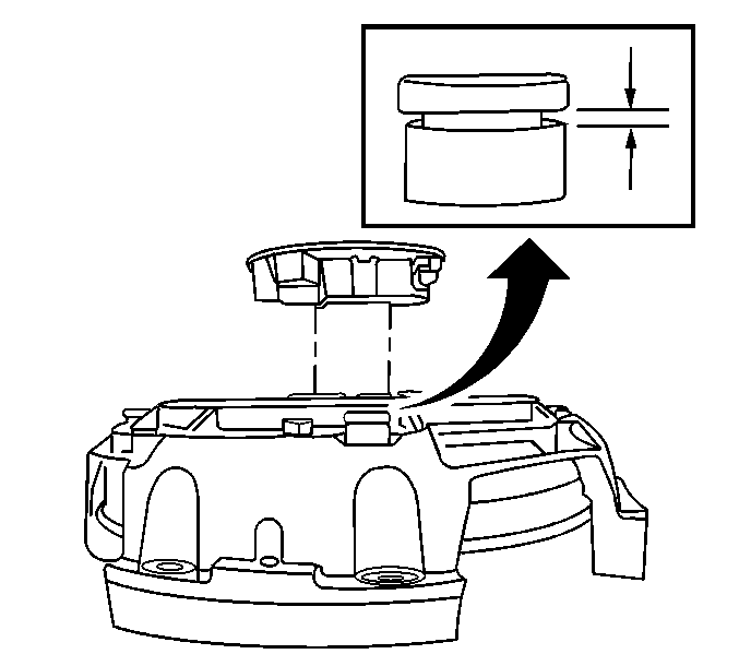
- Remove all 4 bolts. Ensure that there is no gap between the plate spacer roll pin and the tamper proof plate spacer bolt when the clutch pedal is in the up position.
- Depress the clutch pedal (compressing clutch brake) 5 or more times in order for the Solo to automatically reposition the bearing.
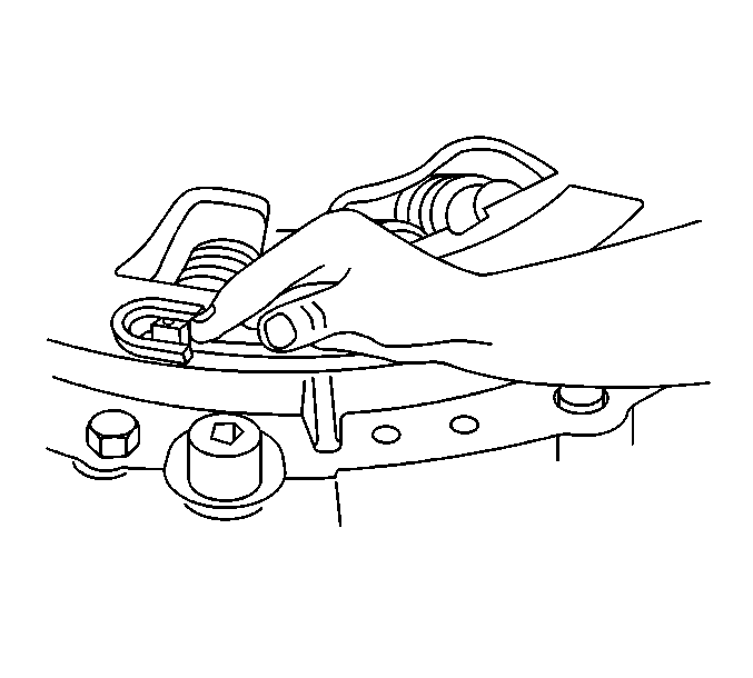
Important: The wear indicating tab should move with finger pressure. Do not force the tab to the "NEW" position.
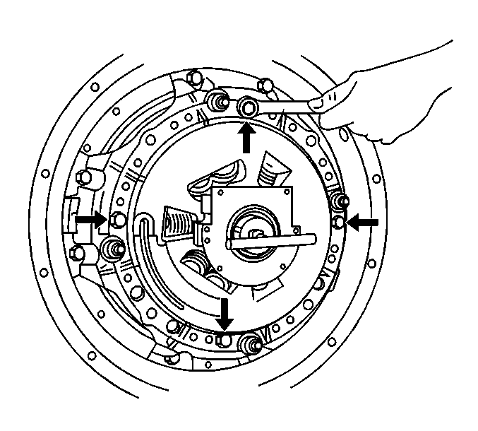
Important: It will be necessary to rotate the flywheel in order to gain access to all 4 clutch pressure plate shipping bolts.
Specification
0.062 gap under each tamper proof plate spacer bolt with the pedal pushed
to the floor.

Clutch Assembly Adjustment MPK ResettingProcedure Out of Vehicle
Important: Use this procedure if transmission and clutch were removed without following correct Removal Procedure.
- Support the clutch in an arbor press with the bearing facing down.
- Center the ram and press downward on the retainer until it comes to a stop. Lock the ram in position.
- Remove the 4 shipping bolts if they have been installed.
- Raise the ram approximately 2.54 mm (1 in).
- Press down on the retainer until it comes to a stop.
- Use finger pressure to slide the clutch wear tab to the left until it is at the NEW position and hold it in this position with a magnet.
- Locate 4 3/8 in x 16 x 1 1/4 in UNC, hex head machine screws. Install them into the 4 cover holes and turn them finger tight.
- Progressively tighten the four shipping bolts in a crisscross pattern until the face of the pressure plate is (0.525 in) below the mounting surface.
- Install the clutch.
Allowing an additional 25.4 mm (1 in) space for the bearing to move down, and allow access to install the four shipping bolts.
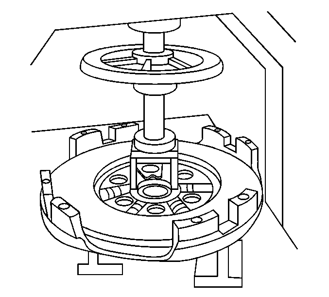
Important: Do not apply excess force on the retainer because the Solo's internal stops can deform the clutch's stamped cover. Eaton recommends using a manually operated arbor press, not a hydraulic press, to avoid distortion of the clutch' stamped cover.

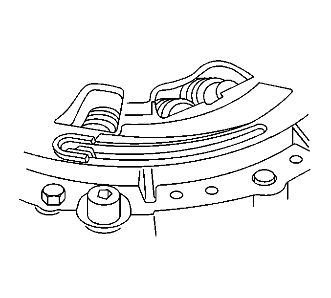
Lock the ram in this position.
Important: Do not apply excess force on the retainer because the Solo's internal stops can deform the clutch's stamped cover. Eaton recommends using a manually operated arbor press, not a hydraulic press, to avoid distortion of the clutch's stamped cover.

Important: You may need to temporarily install slightly longer bolts to allow access of the 1 1/4 in shipping bolts.
Important: This important step will reset the pressure plate spacers and allow the clutch to release after reinstallation.
Clutch Assembly Adjustment Valeo Internal Adjustment
- Disconnect the clutch linkage.
- Measure the distance from the transmission /clutch brake to the release bearing with 25 N·m (6 lb) of force pulling the bearing toward the transmission.
- Verify that adjustment clearance off 99.9 mm (0.750 in) on transmissions without a clutch brake, and 92.7 mm (0.50 in) on transmissions with a clutch brake, has been maintained, after tightening lock nuts.
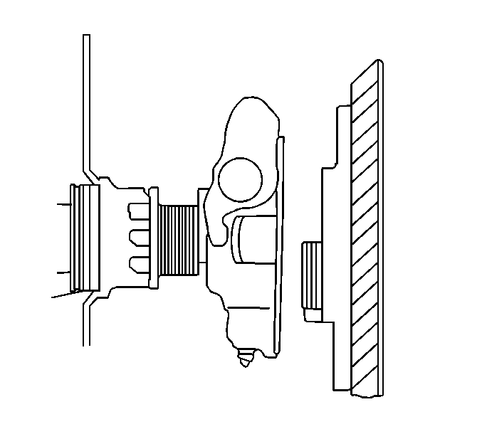
| 2.1. | If 99.9 mm (0.750 in) on transmissions without a clutch brake, no adjustment is necessary. |
| 2.2. | If 92.7 mm (0.50 in) on transmissions with a clutch brake, no adjustment is necessary. |
| 2.3. | If the release bearing position is incorrect, loosen the lock rings and turn the adjusting nut in order to achieve the proper distance. |
| • | Use appropriate spanner wrench to loosen and tighten the lock nuts. |
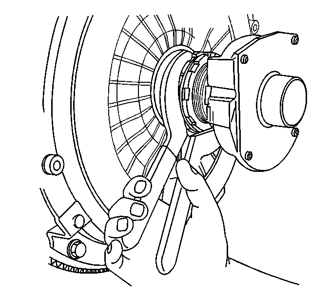
| • | Tighten the lock ring securely against the release lever spider. |
Clutch Assembly Adjustment Lubrication
Sealed Type
Some models are supplied with a sealed release bearing. These are not equipped with a lube fitting and requires no additional grease for the life of the clutch.
Greasable Type
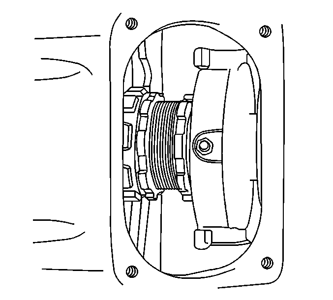
The release bearing has been greased. If the vehicle is in regular service, grease the clutch every 10,000 hours or once per month. If the vehicle is in severe service, grease the clutch every 250 hours or once per month. Only high temperature greases should be used. Chassis lube or all purpose lubricants are not recommended.
Lubrication Procedure
- Apply grease until the grease purges from the bearing housing onto the clutch brake and input shaft. Use a lithium soap base E.P. grease having a minimum +325°F operating range with N.L.G.I. Grade 1 or 2 specs.
- Manually apply lube to the transmission side of the clutch brake and on the input shaft between the brake and the bearing in order to lube the bushing inside the sleeve.
- Apply a small amount of grease between the bearing wear pads and the clutch release fork. Repeat this at normal intervals.
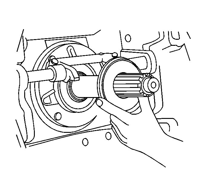
Important: The clutch brake facing is designed to work best when it is coated with grease.
