For 1990-2009 cars only
Special Tools
| • | J 21370-10 Band to Apply Pin Gage |
| • | J 38737 Band Apply Pin Checking Tool |
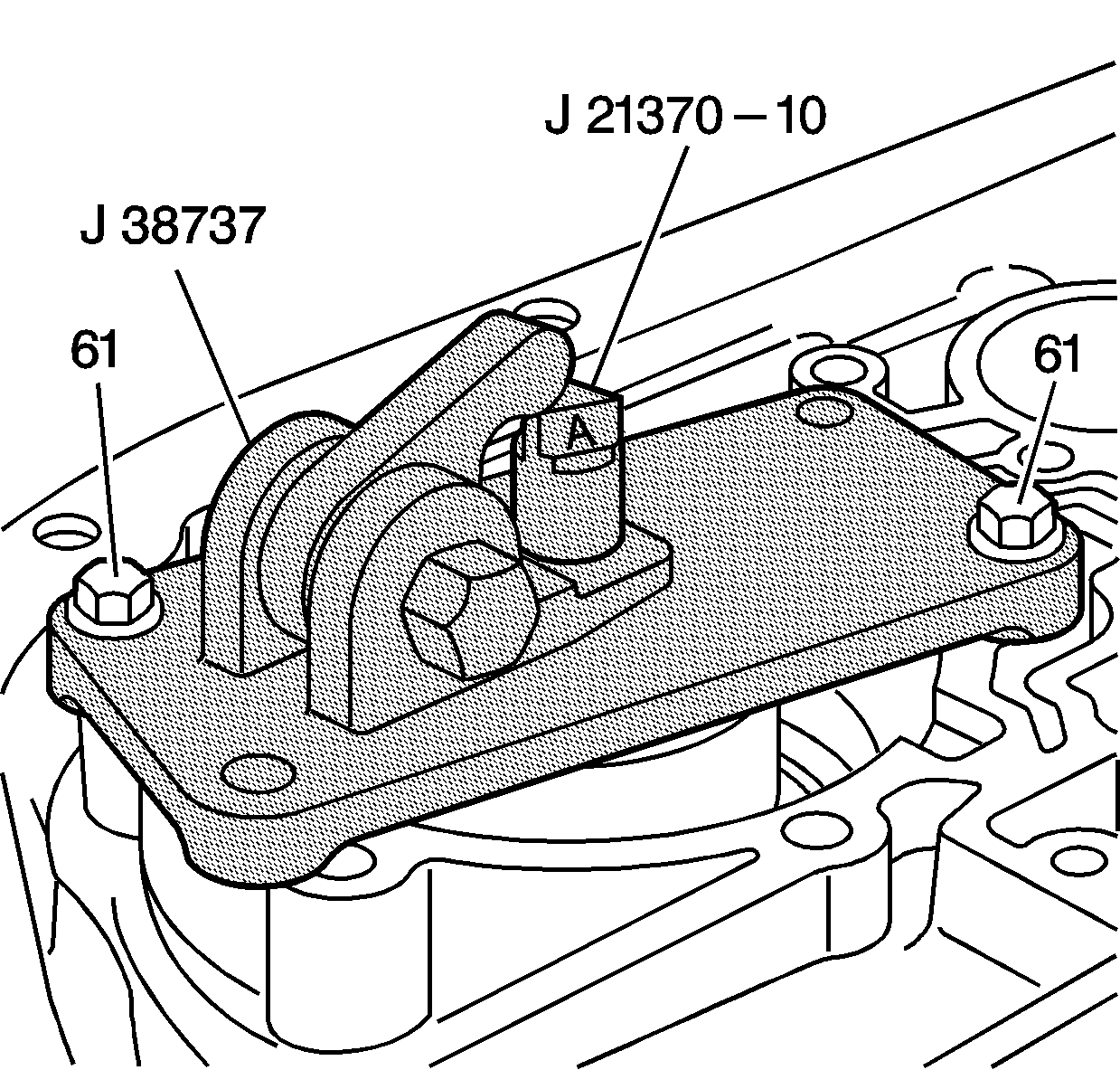
- Install the J 21370-10 pin gage into the low and reverse band servo pin bore.
- Position the J 38737 pin checking tool over the low and reverse band servo bore with the hex hub facing the parking pawl linkage.
- Fasten the J 38737 pin checking tool to the case with 2 low and reverse band servo cover bolts (61) and tighten the bolts to 24 N·m (18 lb ft).
- Verify that the J 21370-10 pin gage moves freely in the J 38737 pin checking tool and in the low and reverse band servo pin bore.
- In order to determine the correct low and reverse band servo piston pin length, tighten the hex hub of the J 38737 pin checking tool to 34 N·m (25 lb ft).
- Observe the lands on the J 21370-10 pin gage in order to determine which land is even with the top edge of the J 38737 pin checking tool . Note the letter (A, B, or C) stamped on the J 21370-10 pin gage .
- Refer to the Low and Reverse Band Servo Piston Pin Specification chart, in the Transmission General Specifications , in order to determine the correct pin length to use.

Caution: Refer to Fastener Caution in the Preface section.
