Removal Procedure
- Remove the upper intake manifold cover from the upper intake manifold.
- Disconnect both the battery negative cables from the batteries. Refer to Battery Negative Cable Disconnection and Connection in Engine Electrical.
- Remove the braces from the turbocharger to the upper intake manifold.
- Remove the boost pressure sensor from the upper intake manifold.
- Remove the intake air temperature sensor from the upper intake manifold.
- Loosen the clamps on the hose between the turbocharger and the upper intake manifold.
- Remove the upper intake manifold from the lower intake manifold.
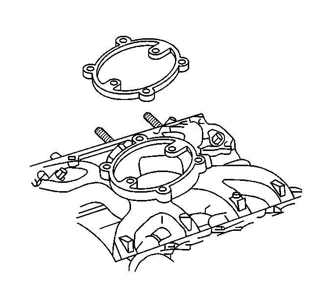
- Remove the upper intake manifold gasket from the lower intake manifold gasket.
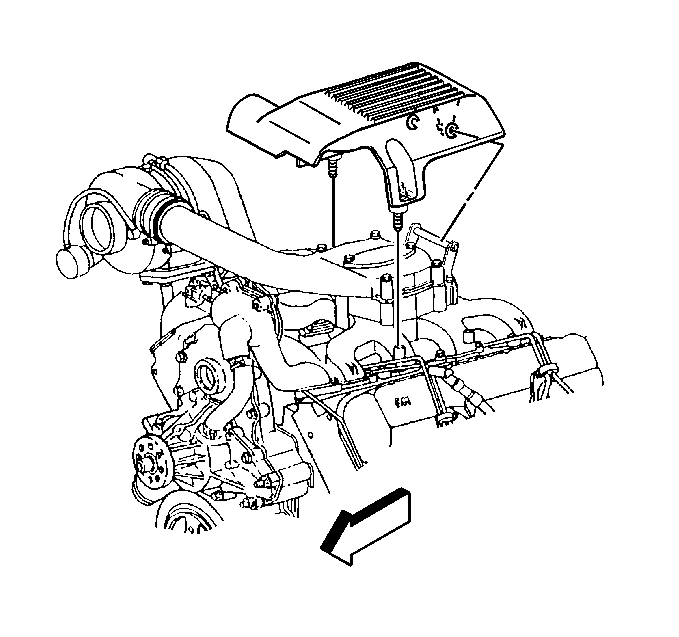
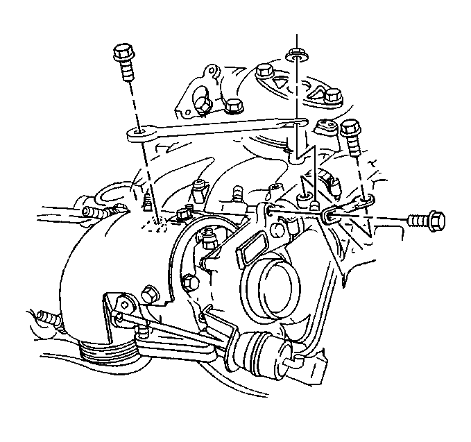
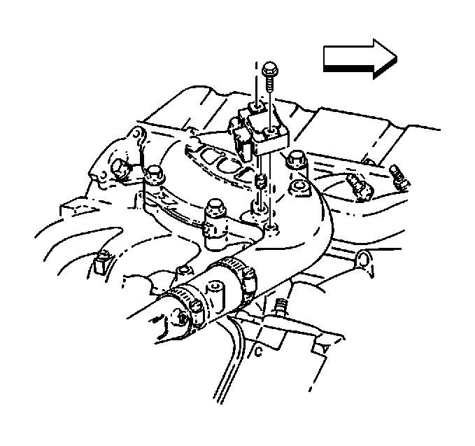
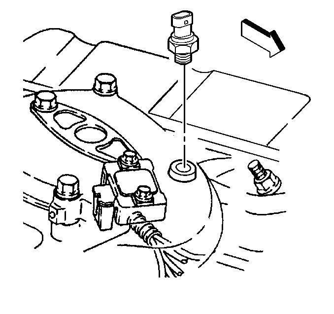
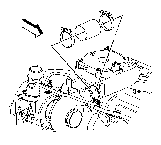
Important: In order to loosen the sealer, run a small screw driver (flat blade) between the hose and the upper intake manifold. Use caution as not to damage the hose.
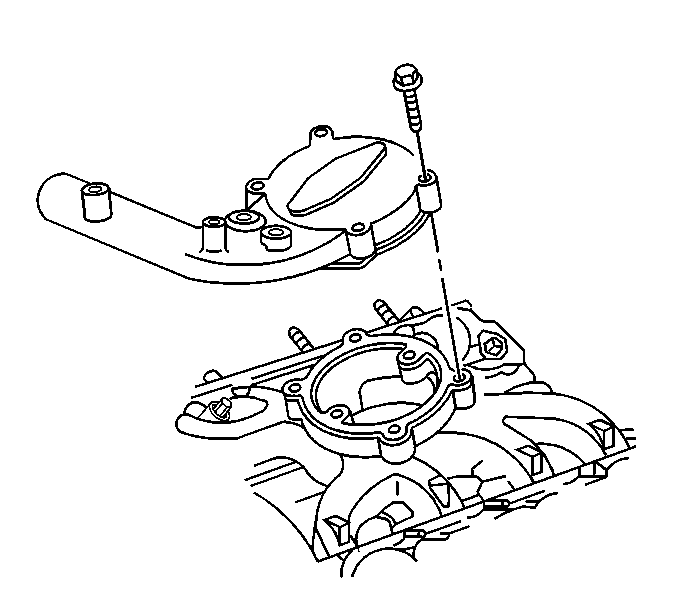
Important: When removing the upper intake manifold, rotate the upper intake manifold in a downward then in an upward motion to help loosen the silicone sealant on the air intake hose.
Installation Procedure
- Apply a small amount of RTV sealant GM P/N 12346286 (Canadian P/N 10953472) to the hose between the turbocharger inlet and the upper intake manifold.
- Install the new upper intake manifold gasket.
- Install the upper intake manifold.
- Install the mounting bolts in the upper intake manifold.
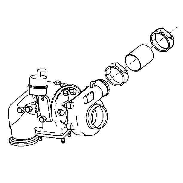
- Tighten the air intake hose clamps on the upper intake manifold.
- Install the boost pressure sensor on the upper intake manifold. Refer to Boost Sensor Replacement in Engine Controls-6.5L-L65.
- Install the intake air temperature sensor to the upper intake manifold. Refer to Intake Air Temperature Sensor Replacement in Engine Controls-6.5L (L65).
- Install the braces from the turbocharger to the upper intake manifold. Refer to Turbocharger Replacement .
- Install the upper engine cover to the upper intake manifold.
- Connect both the battery negative cables to the batteries. Refer to Battery Negative Cable Disconnection and Connection in Engine Electrical.
Important: Install the air intake hose between the upper intake manifold and the turbocharger on the upper intake manifold first before installing the upper intake manifold.


Notice: Use the correct fastener in the correct location. Replacement fasteners must be the correct part number for that application. Fasteners requiring replacement or fasteners requiring the use of thread locking compound or sealant are identified in the service procedure. Do not use paints, lubricants, or corrosion inhibitors on fasteners or fastener joint surfaces unless specified. These coatings affect fastener torque and joint clamping force and may damage the fastener. Use the correct tightening sequence and specifications when installing fasteners in order to avoid damage to parts and systems.
Tighten
Tighten the bolts to 23 N·m (17 lb ft).
Tighten
Tighten the clamps to 6 N·m (50 lb in).

