GM Service Manual Online
For 1990-2009 cars only
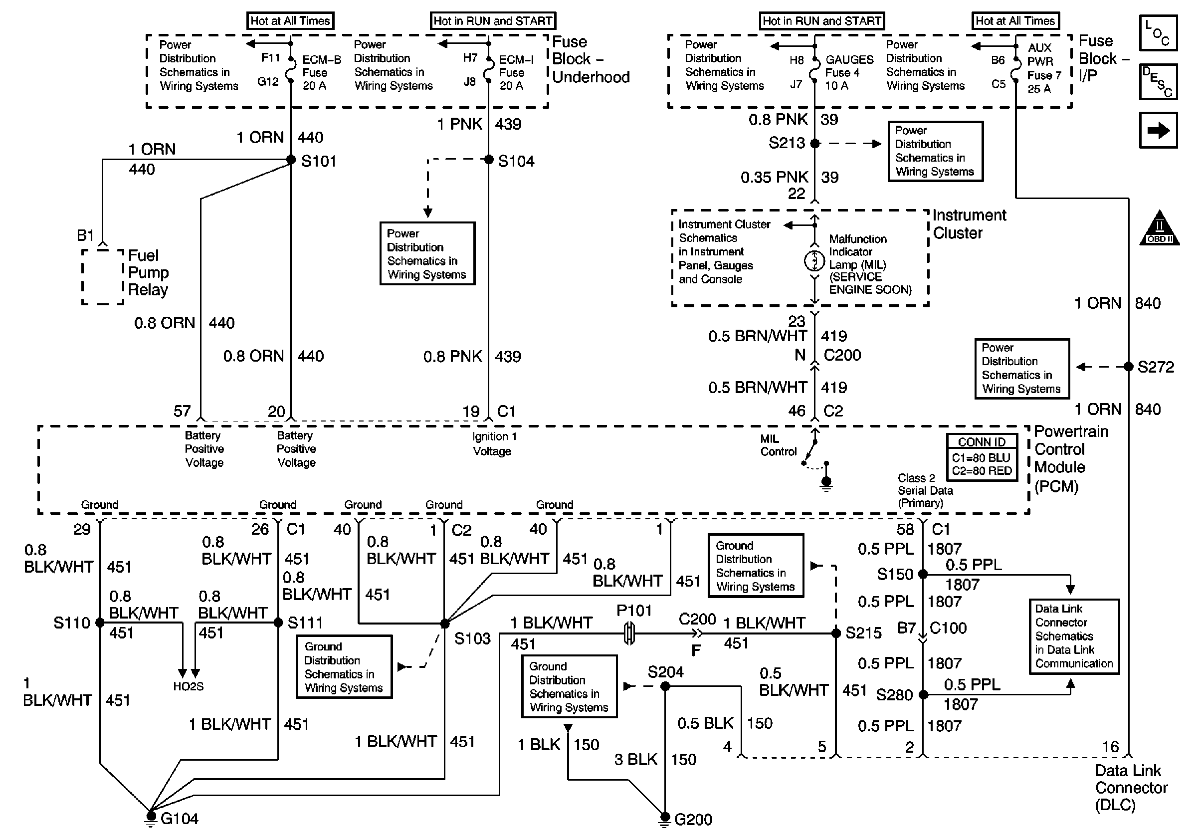
Figure 1:

PCM Power, Grounding, DLC, and MIL


Object Number: 647021  Size: FS
Master Electrical Component List
CMP, CKP, and KS
OBD II Symbol Description Notice
ECM-B, Horn, and A/C Fuses
IGN A Fuse and Ignition Switch
ECM-I Fuse, 1 of 2, Fuel Injectors
IGN A Fuse and Ignition Switch
Indicators and Illumination Lamps
Stop/Haz, Radio Batt, Aux Pwr, and Cig Ltr Fuses
Gauges Fuse and Turn-B/U Fuse
Stop/Haz, Radio Batt, Aux Pwr, and Cig Ltr Fuses
Data Link Connector
G104, L18, 1 of 2, All Except HO2S Circuit
G200
G104, L18, 1 of 2, All Except HO2S Circuit
HO2S Circuit
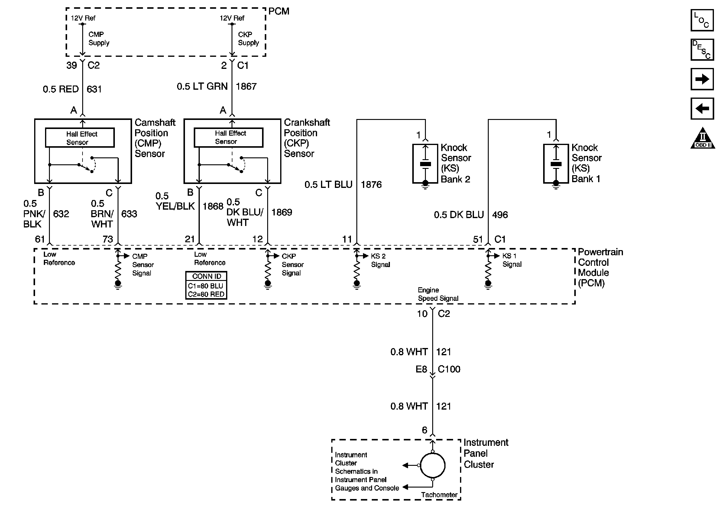
Figure 2:

CMP, CKP, and KS


Object Number: 647022  Size: FS
Master Electrical Component List
Knock Sensor (KS) System Description
Ignition Control, Bank 1 (Left Side)
PCM Power, Grounding, DLC, and MIL
OBD II Symbol Description Notice
Speedometer, Tachometer, and Fuel Gauge
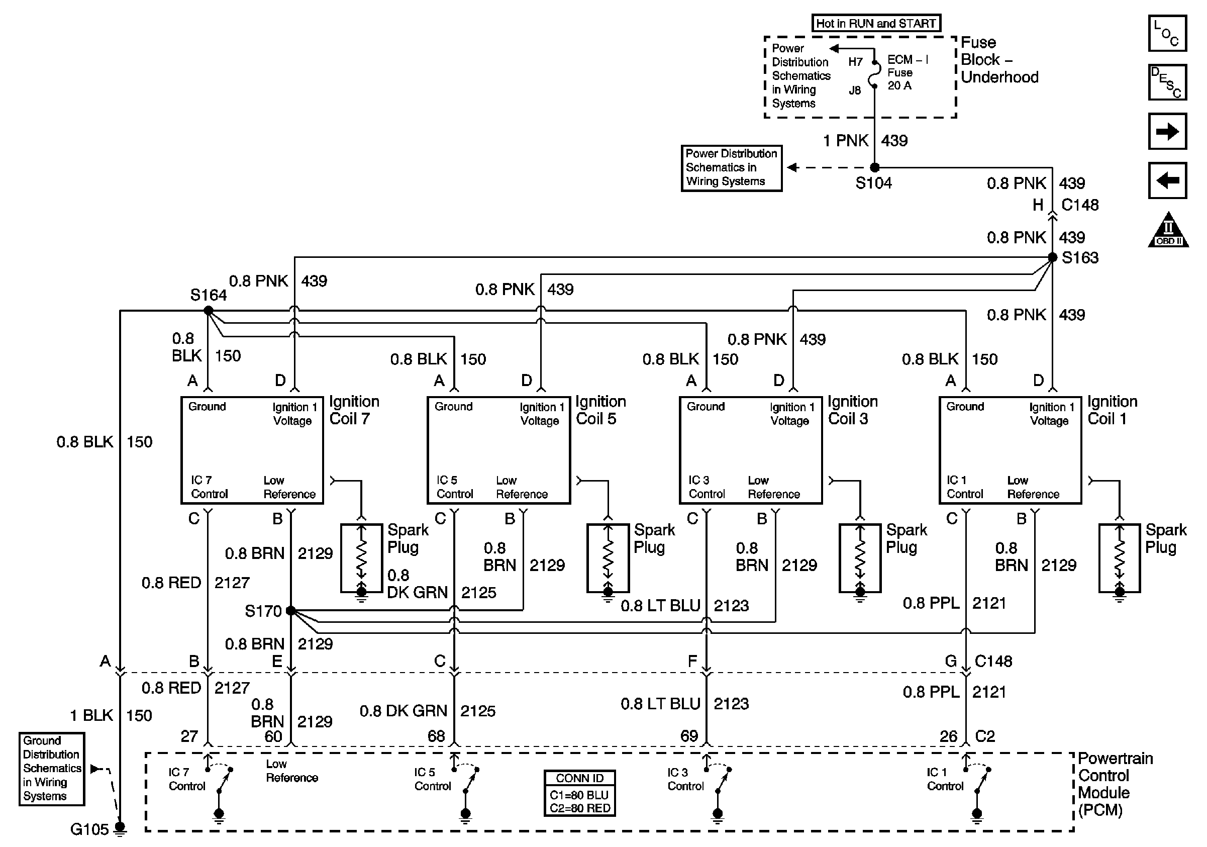
Figure 3:

Ignition Control, Bank 1 (Left Side)


Object Number: 647023  Size: FS
Master Electrical Component List
Electronic Ignition (EI) System Description
Ignition Control, Bank 2 (Right Side)
CMP, CKP, and KS
OBD II Symbol Description Notice
IGN A Fuse and Ignition Switch
ECM-I Fuse, 2 of 2, Ignition Coils
G105, L18, 2 of 2, Ignition Coils
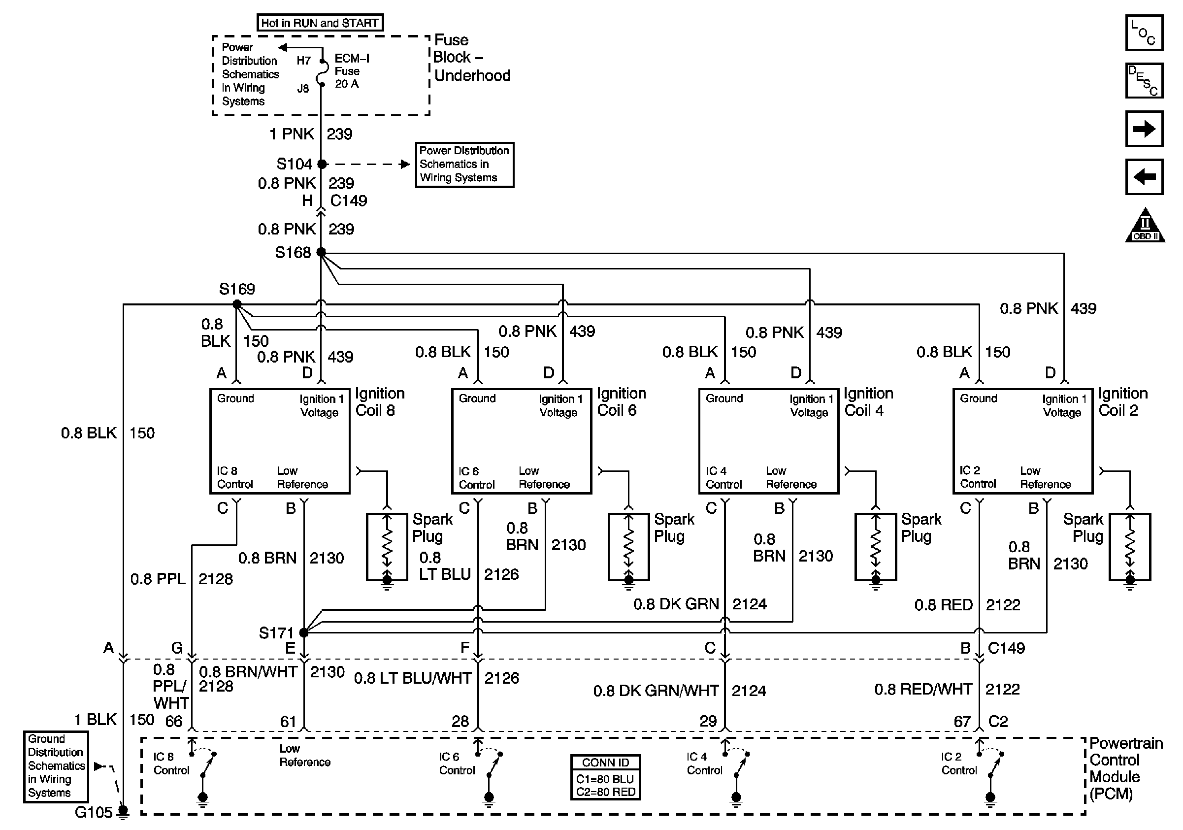
Figure 4:

Ignition Control, Bank 2 (Right Side)


Object Number: 647026  Size: FS
Master Electrical Component List
Electronic Ignition (EI) System Description
Fuel Pump Controls, Single Tank
Ignition Control, Bank 1 (Left Side)
OBD II Symbol Description Notice
IGN A Fuse and Ignition Switch
ECM-I Fuse, 2 of 2, Ignition Coils
G105, L18, 2 of 2, Ignition Coils
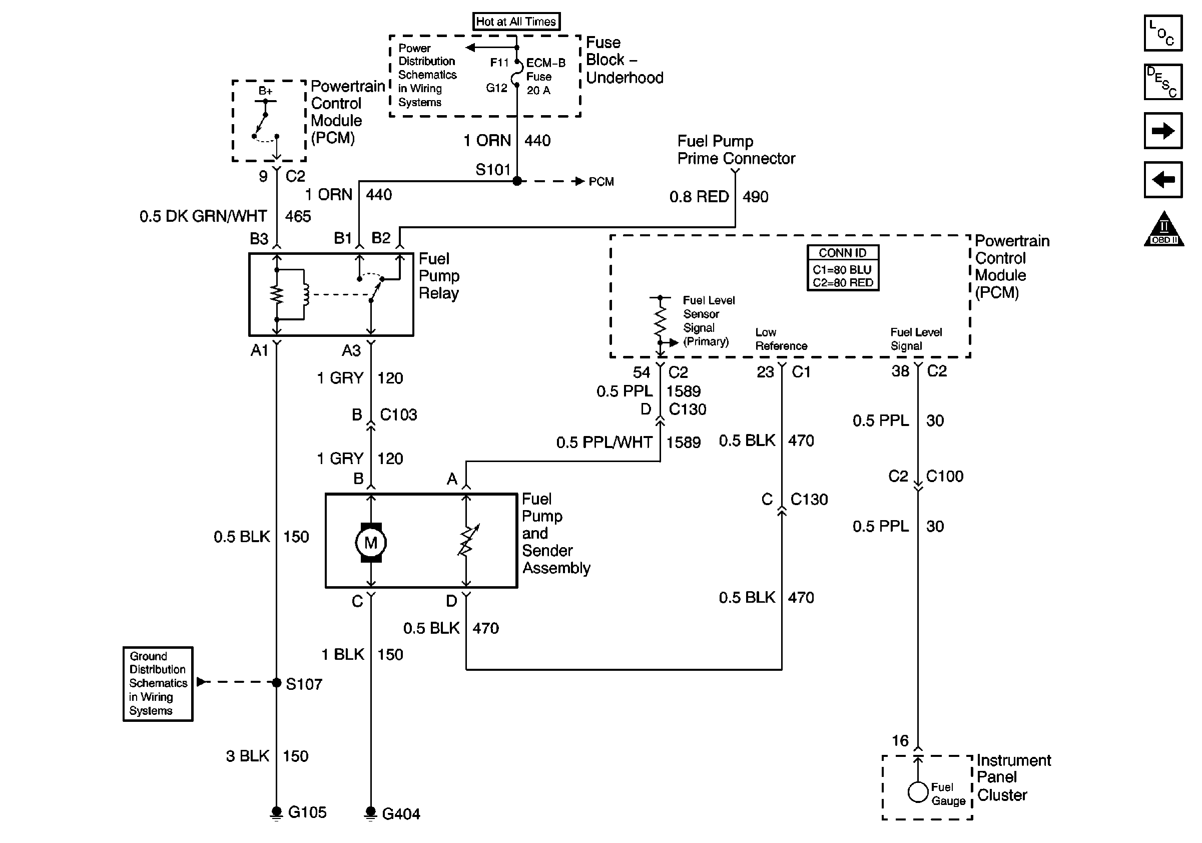
Figure 5:

Fuel Pump Controls, Single Tank


Object Number: 647027  Size: FS
Master Electrical Component List
Fuel Pump Controls, Dual Tanks
Ignition Control, Bank 2 (Right Side)
OBD II Symbol Description Notice
Battery and Underhood Fuse Block
PCM Power, Grounding, DLC, and MIL
Speedometer, Tachometer, and Fuel Gauge
G105, L18, 1 of 2, All Except Ignition Coils
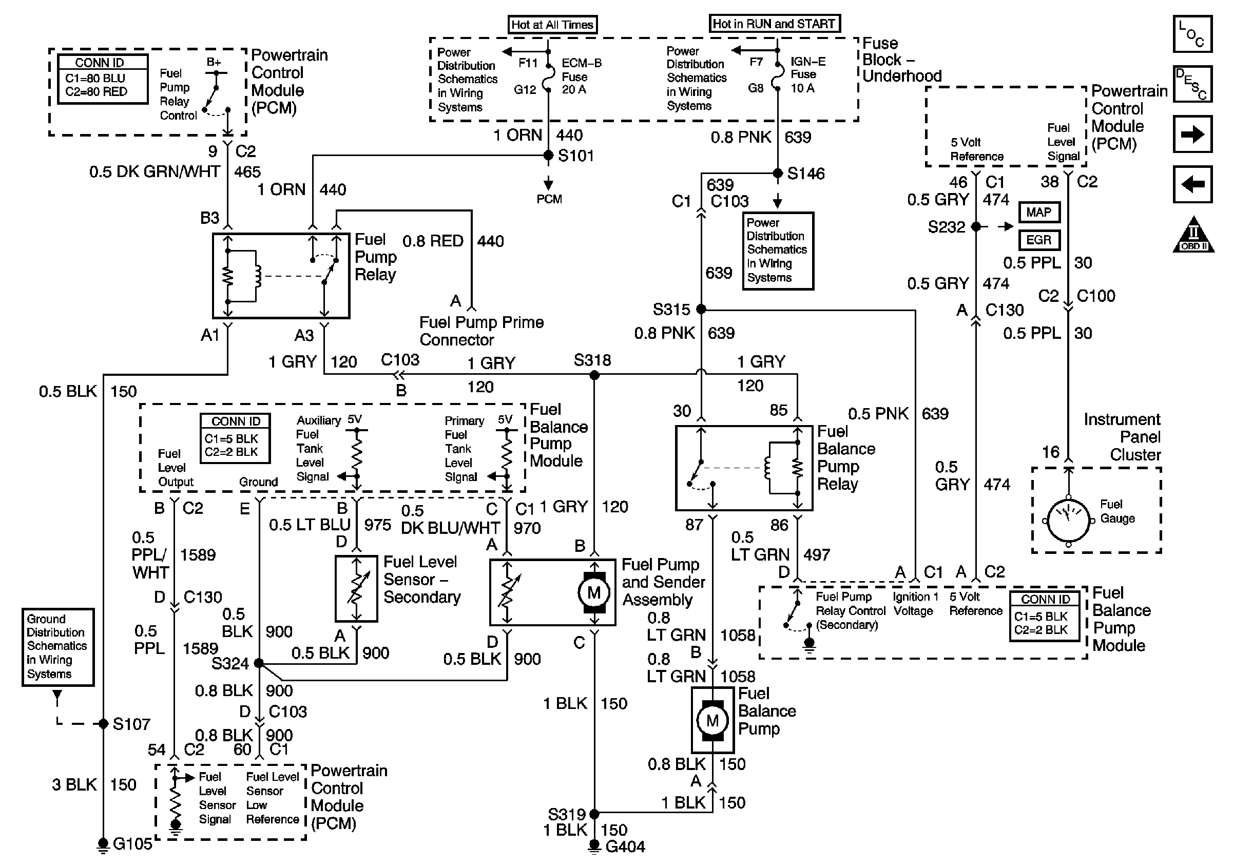
Figure 6:

Fuel Pump Controls, Dual Tanks


Object Number: 647028  Size: FS
Master Electrical Component List
Fuel Injector Controls
Fuel Pump Controls, Single Tank
OBD II Symbol Description Notice
Battery and Underhood Fuse Block
PCM Power, Grounding, DLC, and MIL
IGN A Fuse and Ignition Switch
ENG I and IGN-E Fuse - L18
MAP, ECT, and Air Meter (IAC&MAF)
EVAP and EGR
Speedometer, Tachometer, and Fuel Gauge
G105, L18, 1 of 2, All Except Ignition Coils
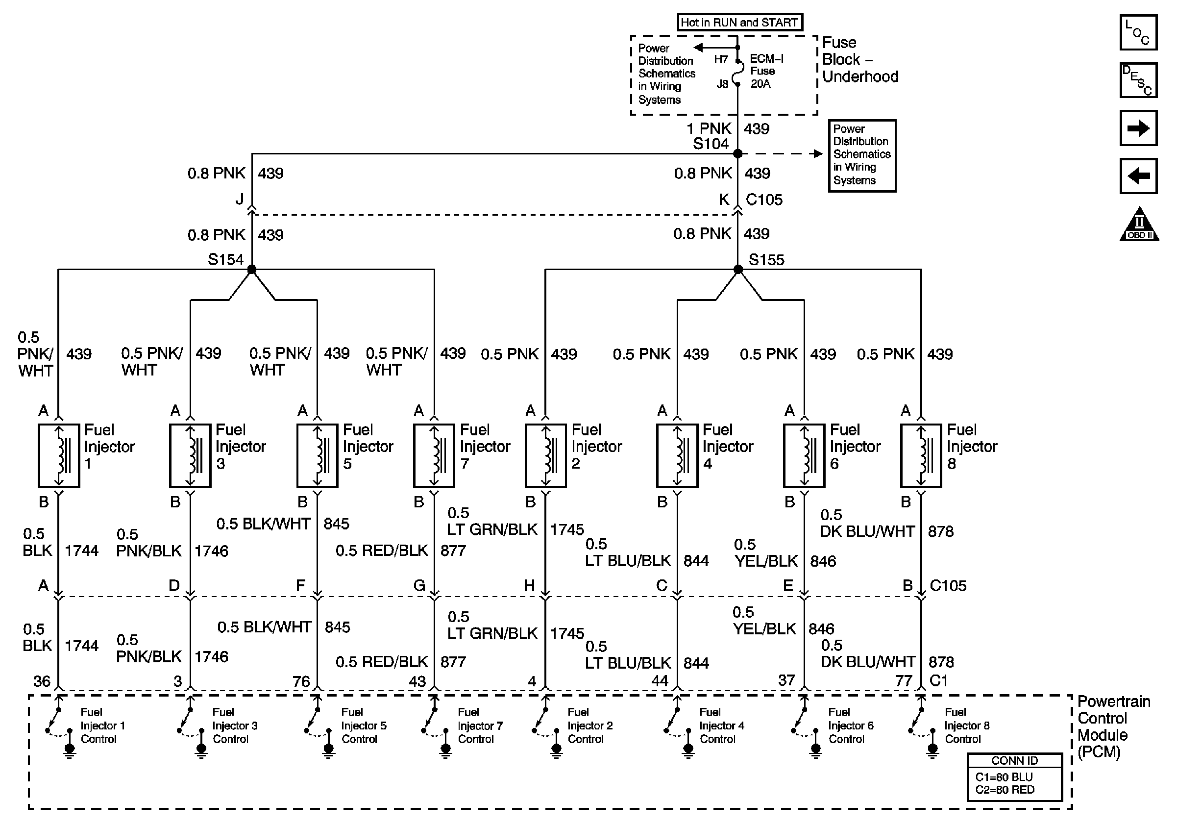
Figure 7:

Fuel Injector Controls


Object Number: 647029  Size: FS
Master Electrical Component List
MAP, ECT, and Air Meter (IAC&MAF)
Fuel Pump Controls, Dual Tanks
OBD II Symbol Description Notice
IGN A Fuse and Ignition Switch
ECM-I Fuse, 1 of 2, Fuel Injectors
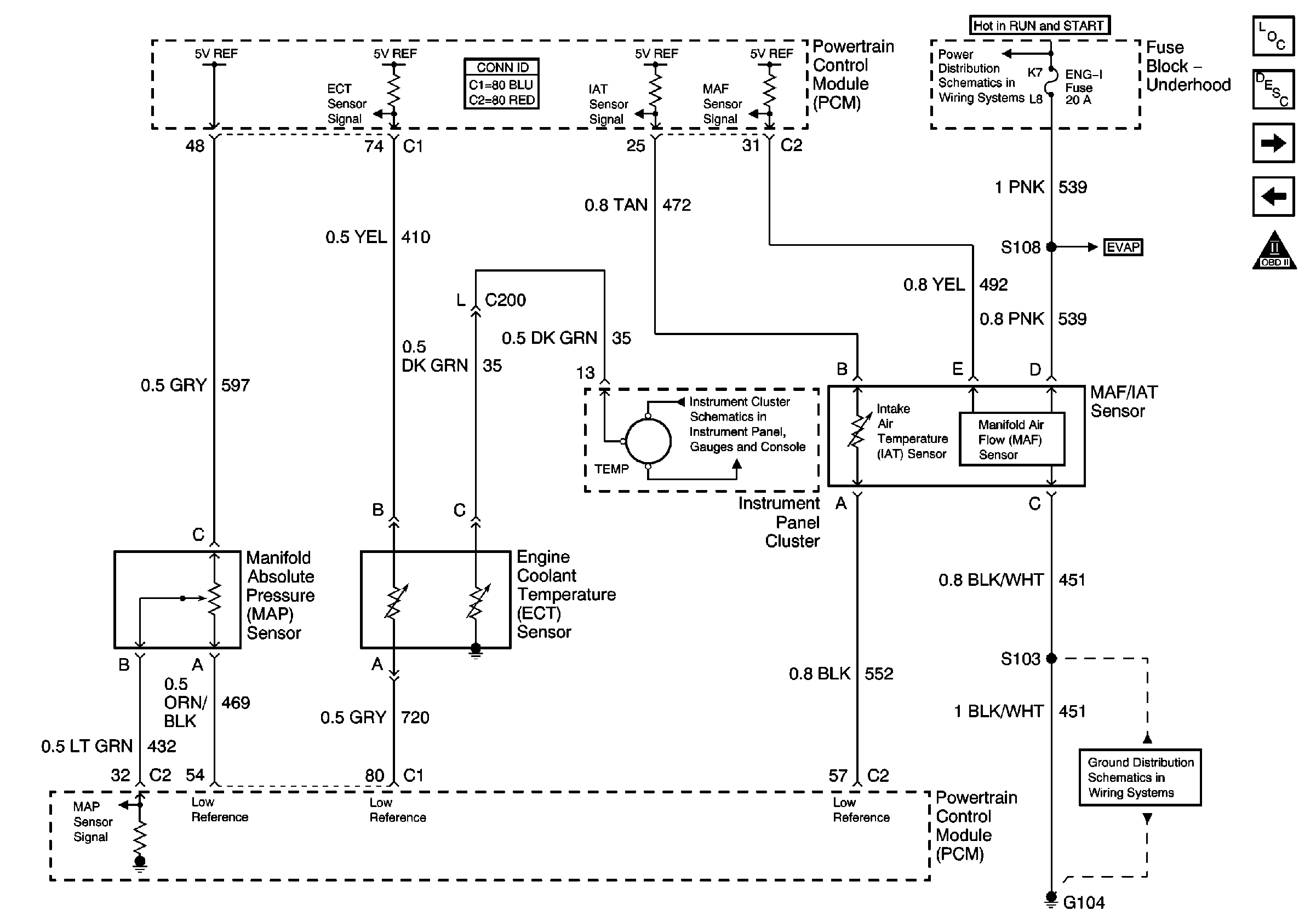
Figure 8:

MAP, ECT, and Air Meter (IAC&MAF)


Object Number: 647032  Size: FS
Master Electrical Component List
Powertrain Control Module Description
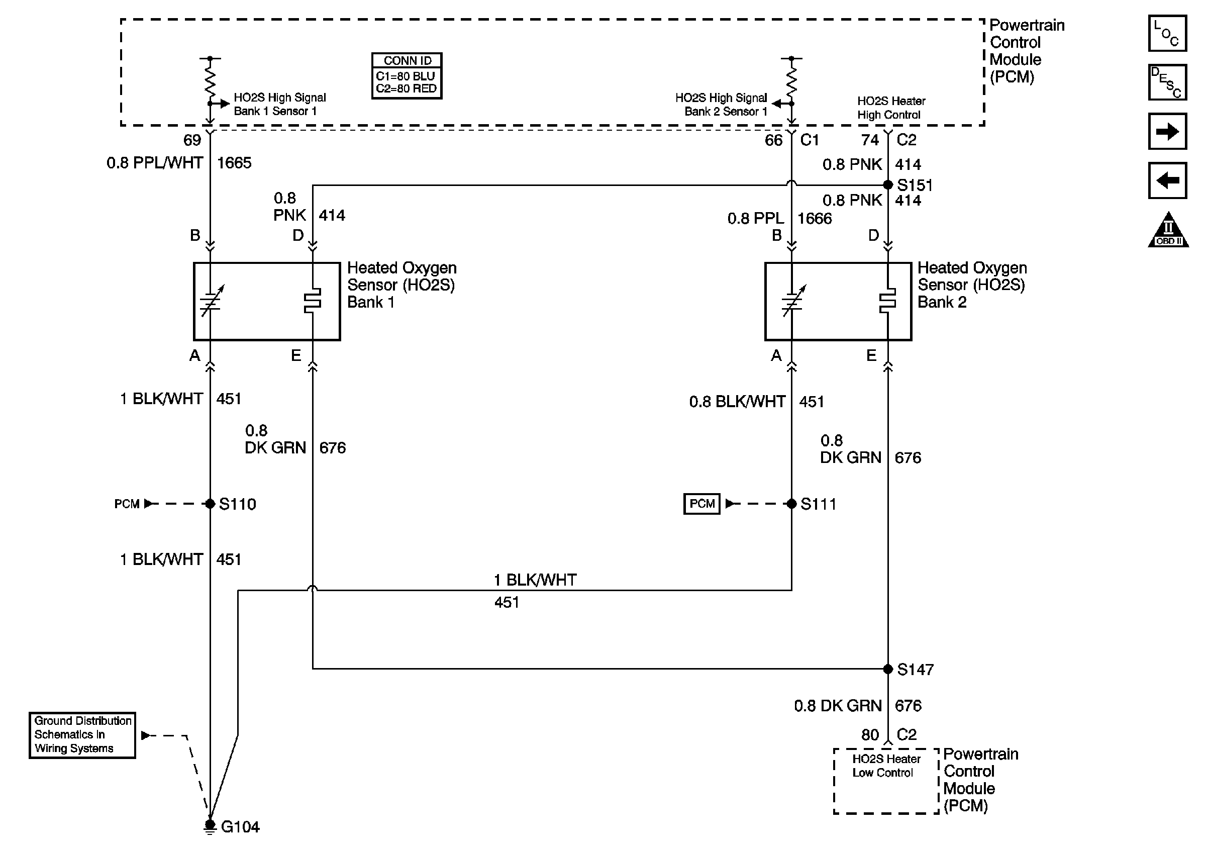
HO2S Circuit
Fuel Injector Controls
OBD II Symbol Description Notice
IGN A Fuse and Ignition Switch
EVAP and EGR
G104, L18, 1 of 2, All Except HO2S Circuit
Oil Pressure, Coolant Temperature, and Voltage Gauges, Battery and Check Gauges Indicators
Figure 9:

HO2S Circuit


Object Number: 647035  Size: FS
Master Electrical Component List
Powertrain Control Module Description
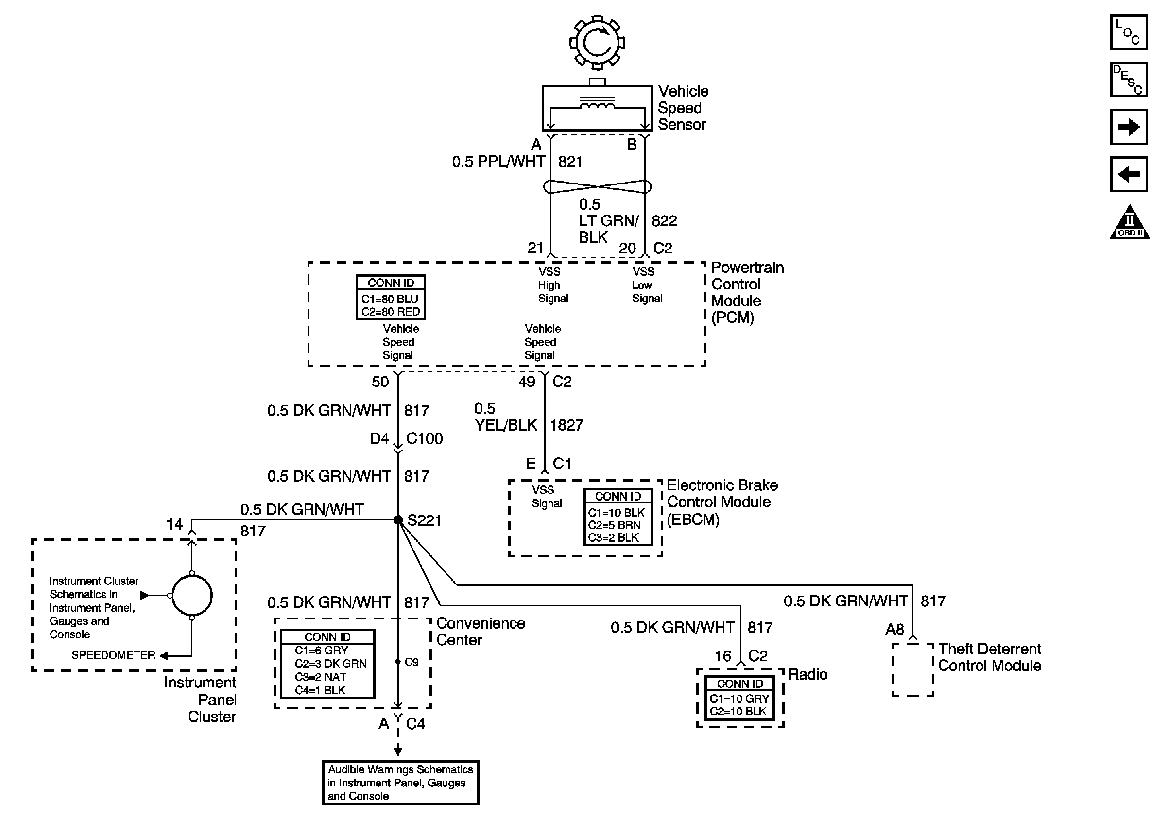
VSS Circuit
MAP, ECT, and Air Meter (IAC&MAF)
OBD II Symbol Description Notice
PCM Power, Grounding, DLC, and MIL
G104, L18, 1 of 2, All Except HO2S Circuit
PCM Power, Grounding, DLC, and MIL
Figure 10:

VSS Circuit


Object Number: 647036  Size: FS
Master Electrical Component List
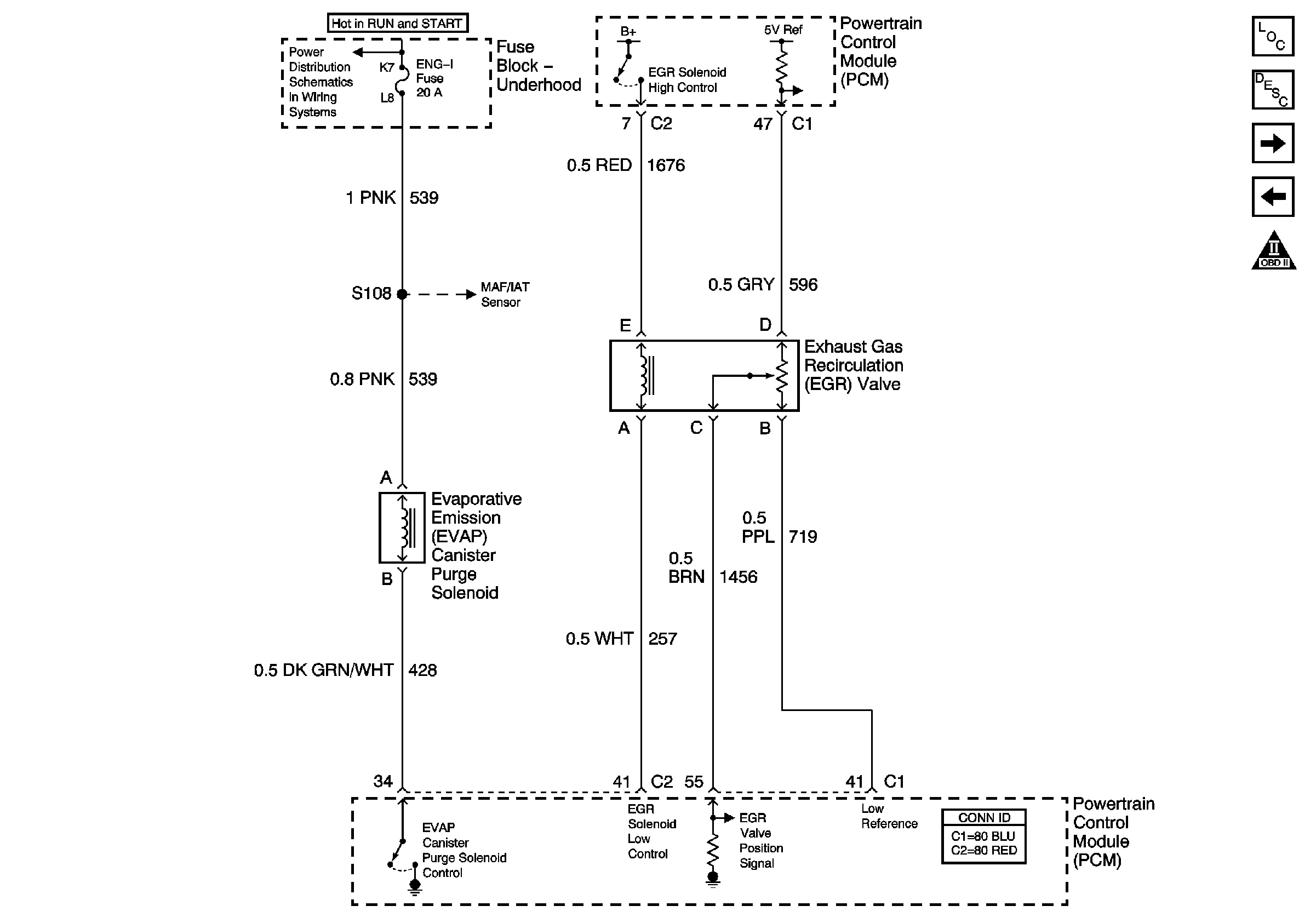
EVAP and EGR
HO2S Circuit
OBD II Symbol Description Notice
Speedometer, Tachometer, and Fuel Gauge
Audible Warnings Circuit
Figure 11:

EVAP and EGR


Object Number: 647038  Size: FS
Master Electrical Component List
Exhaust Gas Recirculation (EGR) System Description
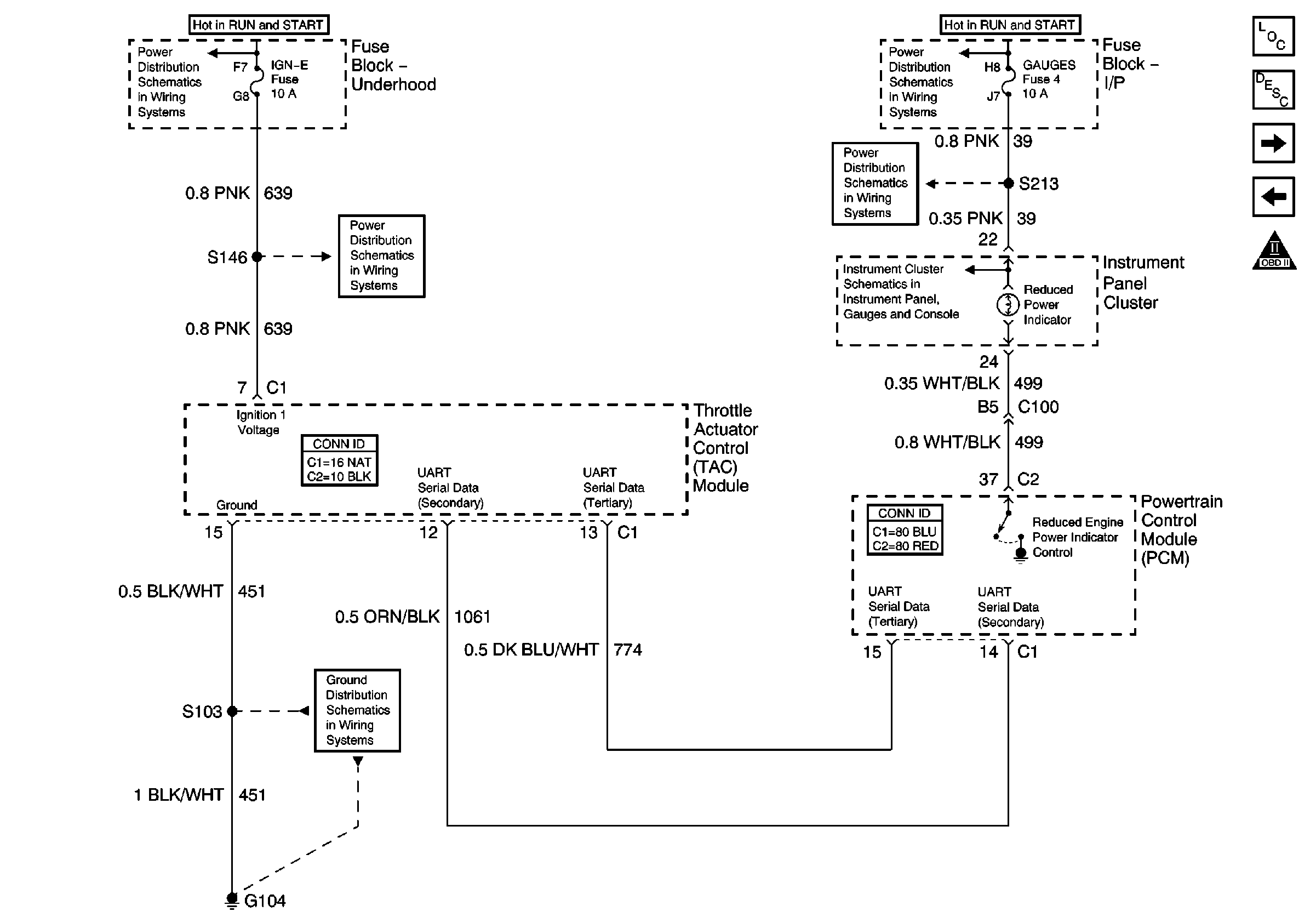
TAC Power, Grounding, Data Circuits, and Indicator Control
VSS Circuit
OBD II Symbol Description Notice
IGN A Fuse and Ignition Switch
MAP, ECT, and Air Meter (IAC&MAF)
Figure 12:

TAC Power, Grounding, Data Circuits, and Indicator Control


Object Number: 647040  Size: FS
Master Electrical Component List
Throttle Actuator Control (TAC) System Description
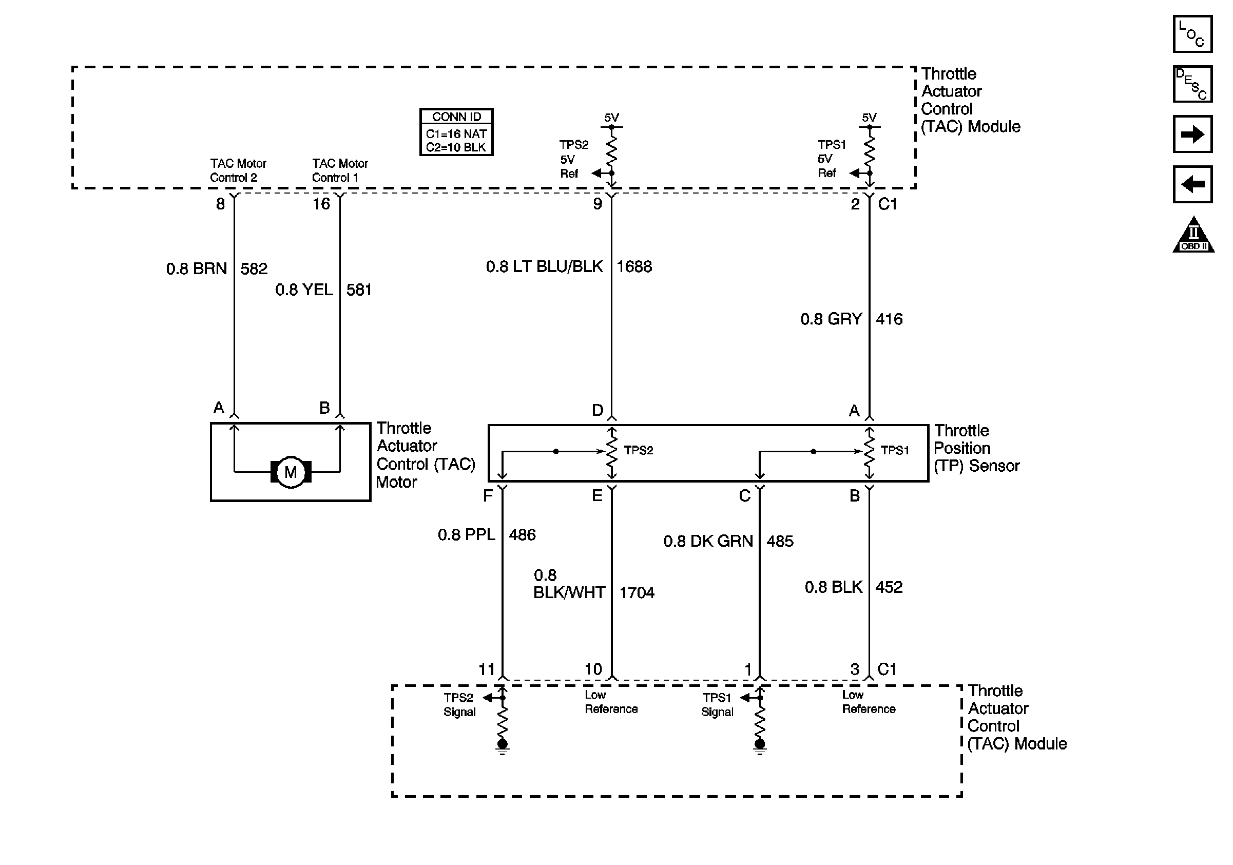
Throttle Control Circuits
EVAP and EGR
OBD II Symbol Description Notice
IGN A Fuse and Ignition Switch
ENG I and IGN-E Fuse - L18
G104, L18, 1 of 2, All Except HO2S Circuit
IGN A Fuse and Ignition Switch
Gauges Fuse and Turn-B/U Fuse
Indicators and Illumination Lamps
Figure 13:

Throttle Control Circuits


Object Number: 647042  Size: FS
Master Electrical Component List
Throttle Actuator Control (TAC) System Description
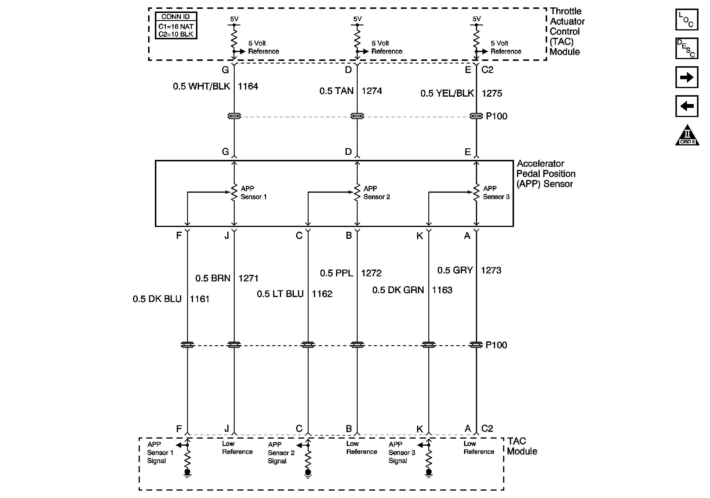
Accelerator Pedal Position Sensor Circuits
TAC Power, Grounding, Data Circuits, and Indicator Control
OBD II Symbol Description Notice
Figure 14:

Accelerator Pedal Position Sensor Circuits


Object Number: 647044  Size: FS
Master Electrical Component List
Throttle Actuator Control (TAC) System Description
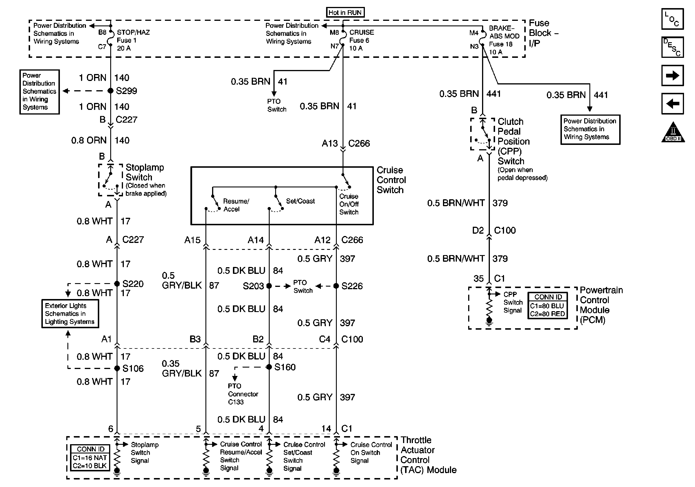
TAC Cruise Control Inputs
Throttle Control Circuits
OBD II Symbol Description Notice
Figure 15:

TAC Cruise Control Inputs


Object Number: 647045  Size: FS
Master Electrical Component List
Throttle Actuator Control (TAC) System Description
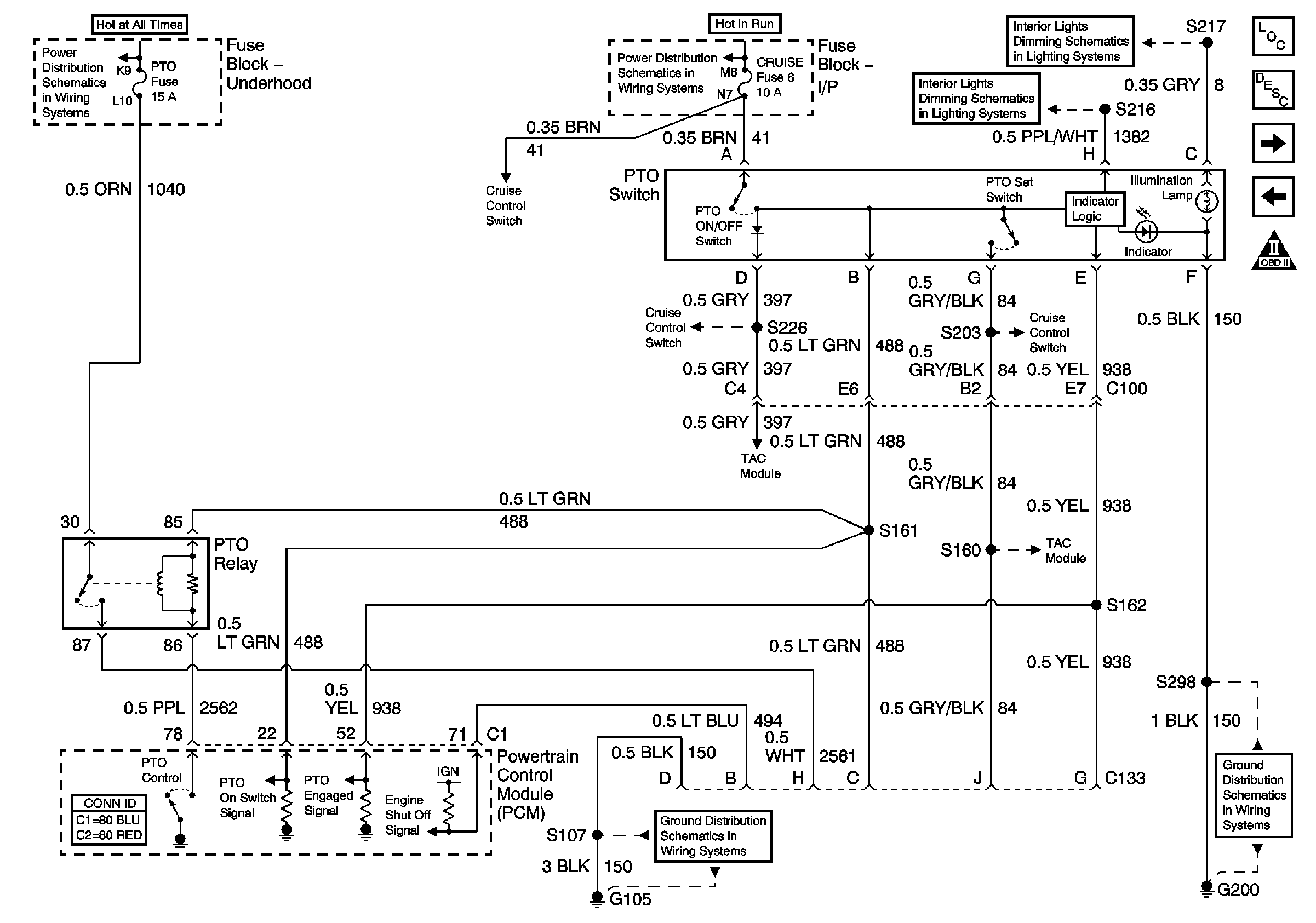
PTO Control Provisions
Accelerator Pedal Position Sensor Circuits
OBD II Symbol Description Notice
Stop/Haz, Radio Batt, Aux Pwr, and Cig Ltr Fuses
Lighting and Battery Fuses
ABS, Blower, Stop-Haz, and IGN B Fuses, and Ignition Switch
PTO Control Provisions
Brake, Cruise, SEO TP-2, and Htr-A/C Fuses
PTO Control Provisions
Stop and Turn/Hazard Lamps Controls
Figure 16:

PTO Control Provisions


Object Number: 647046  Size: FS
Master Electrical Component List
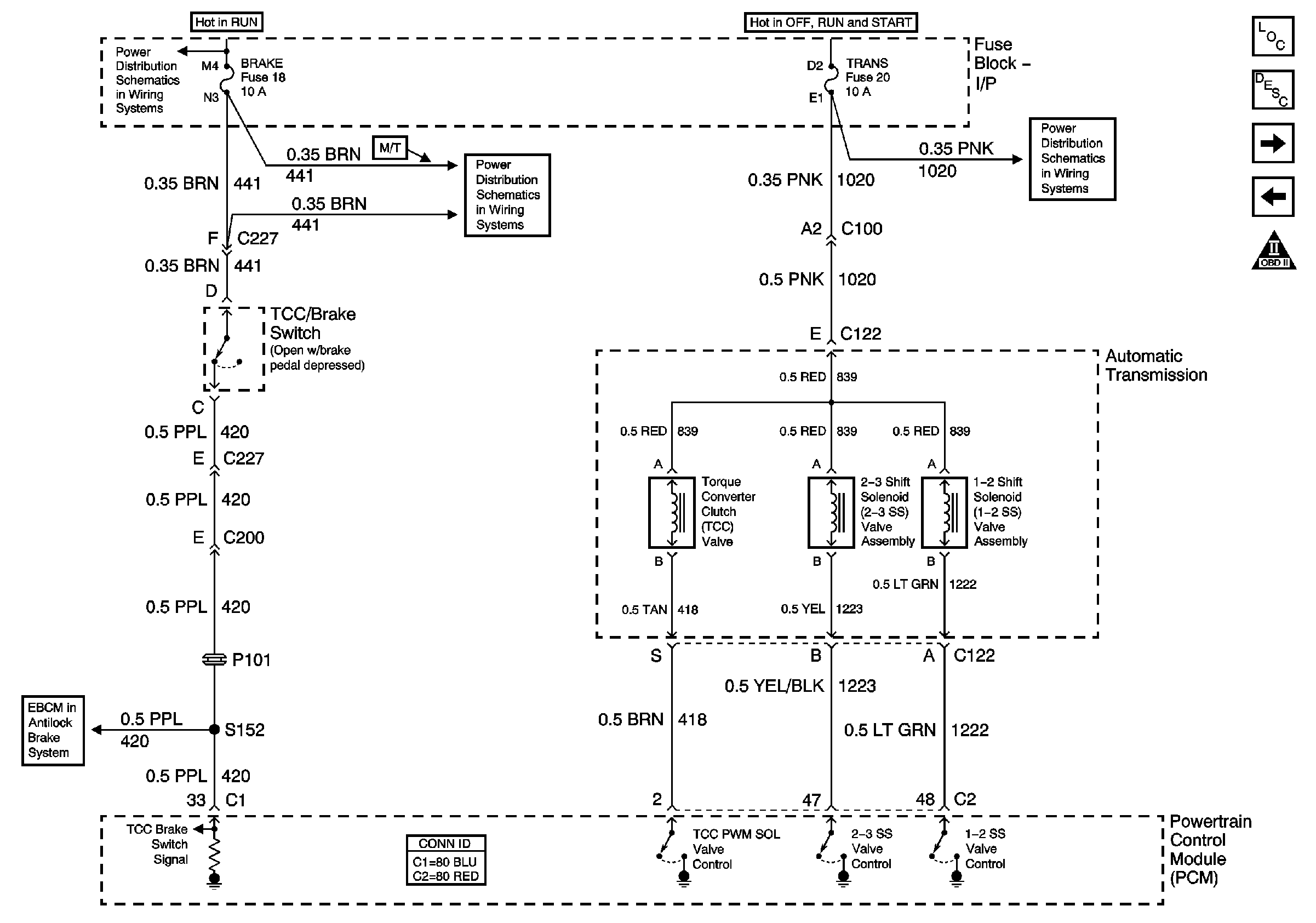
A/T TCC/Stop Lamp Switch, Shift Solenoids
TAC Cruise Control Inputs
OBD II Symbol Description Notice
Battery and Underhood Fuse Block
TAC Cruise Control Inputs
ABS, Blower, Stop-Haz, and IGN B Fuses, and Ignition Switch
Instrument Lamps Dimming Circuits
TAC Cruise Control Inputs
G200
TAC Cruise Control Inputs
G105, L18, 1 of 2, All Except Ignition Coils
Figure 17:

A/T TCC/Stop Lamp Switch, Shift Solenoids


Object Number: 647048  Size: FS
Master Electrical Component List
Electronic Component Description
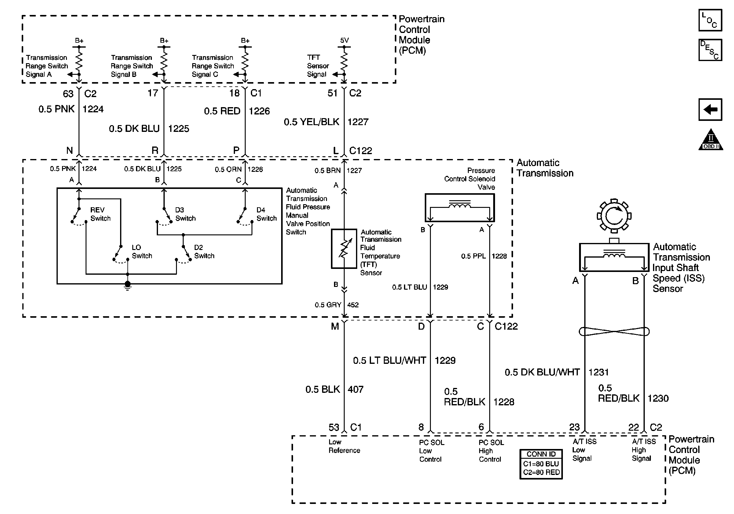
A/T Internal Switches, TFT, PC Solenoid Valve
PTO Control Provisions
OBD II Symbol Description Notice
ABS, Blower, Stop-Haz, and IGN B Fuses, and Ignition Switch
Brake, Cruise, SEO TP-2, and Htr-A/C Fuses
IGN A Fuse and Ignition Switch
Pwr Wdos Circuit Breaker, Wiper, Radio, Clock, and Trans Fuses
EBCM Stoplamp Switch and Wheel Speed Inputs
Figure 18:

A/T Internal Switches, TFT, PC Solenoid Valve


Object Number: 647049  Size: FS
Master Electrical Component List
Electronic Component Description
A/T TCC/Stop Lamp Switch, Shift Solenoids
OBD II Symbol Description Notice