Intake Manifold Removal G
Thermostat Housing
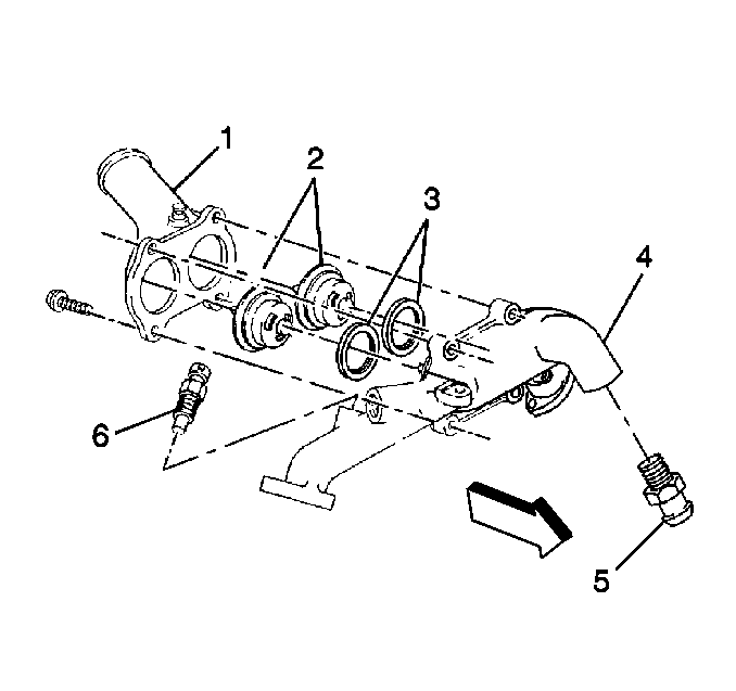
- Remove the upper thermostat
housing retaining bolts from the lower thermostat housing.
- Remove the upper thermostat housing (1).
- Remove the thermostats (2) with the seals (3).
- Remove the thermostat seals (3) from the thermostats (2).
- Remove the heater flow control valve.
- Remove the engine coolant temperature (ECT) sensor (6) from the
lower thermostat housing.
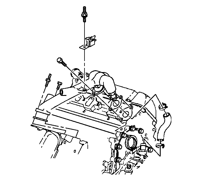
- Remove the fuel bleed
valve retaining nut.
- Remove the fuel bleed valve.
- Remove the fuel bleed valve mounting bolt.
- Loosen the thermostat bypass hose retaining clamps.
- Remove the lower thermostat housing retaining bolts.
- Remove the lower thermostat housing.
- Remove the gaskets.
- Remove the thermostat bypass hose.
- Remove the thermostat bypass hose retaining clamps.
- Remove the thermostat bypass hose fitting.
Intake Manifold
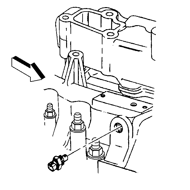
- Disconnect the intake air temperature (IAT) sensor electrical connector.
- Remove the IAT sensor.
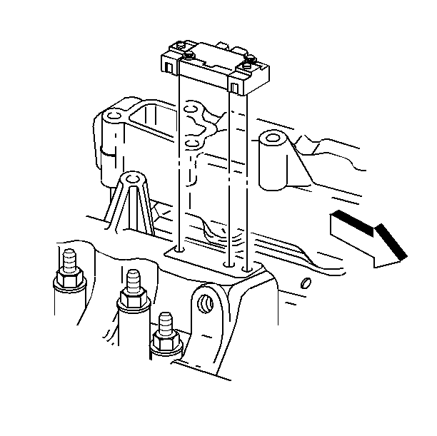
- Disconnect the manifold
absolute pressure (MAP) sensor electrical connector.
- Remove the MAP sensor retaining bolts.
- Remove the MAP sensor.
- Remove the gasket.
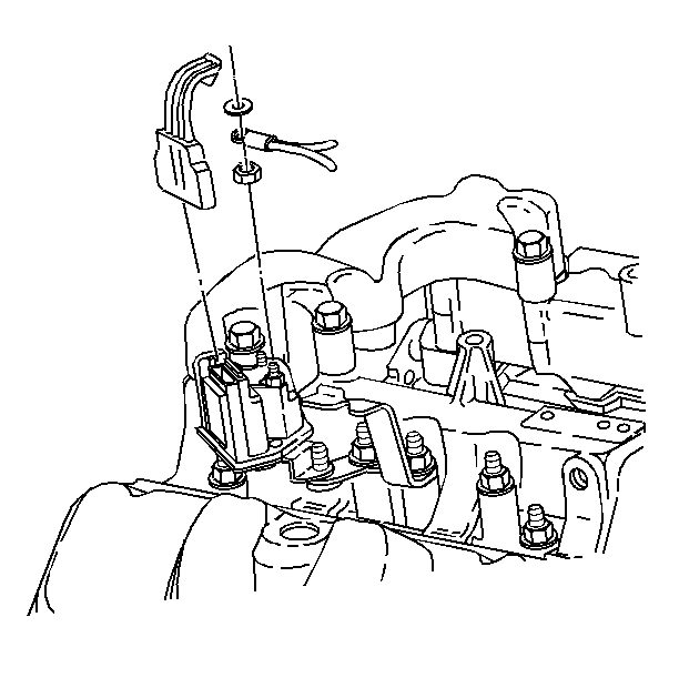
- Disconnect the glow plug
relay electrical connectors.
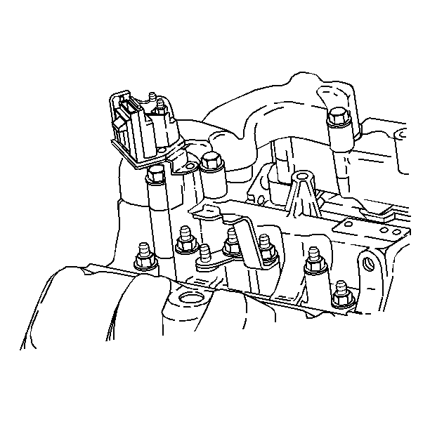
- Remove the glow plug relay
retaining nuts.
- Remove the glow plug relay.
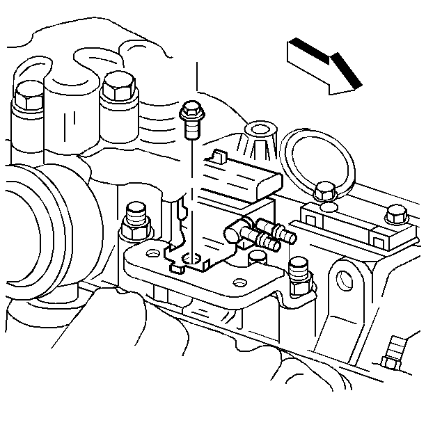
- Disconnect the vacuum
harness hose connectors.
- Remove the vacuum harness.
- Remove the vacuum solenoid retaining bolt(s).
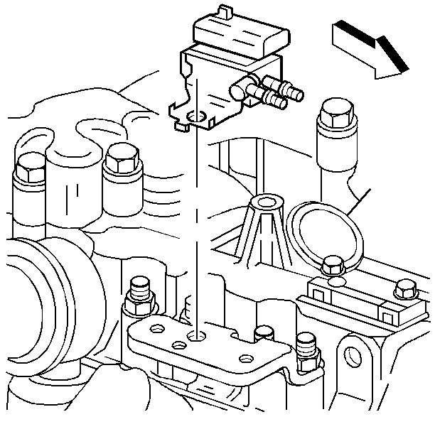
- Remove the vacuum solenoid(s).
- Remove the vacuum solenoid mounting bracket retaining nuts.
- Remove the vacuum solenoid mounting bracket.
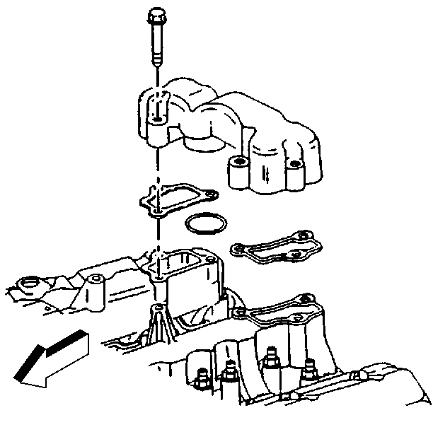
- Remove the upper intake
manifold retaining bolts.
- Remove the upper intake manifold.
- Remove the O-ring from the upper intake manifold.
- Remove the gaskets.
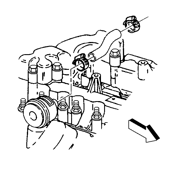
- Loosen the crankcase depression regulator (CDR) valve vent hose clamp
at the CDR valve.
- Remove the CDR valve vent hose from the CDR valve.
- Remove the CDR valve vent hose clamp from the CDR valve vent hose.
- Remove the CDR valve from the valve rocker arm cover. Pull upward
while twisting/rocking CDR valve.
- Remove the fuel injection feed pipe mounting bracket retaining
nuts.
- Remove the fuel injection feed pipe mounting brackets.
- Remove the fuel injection feed pipes.
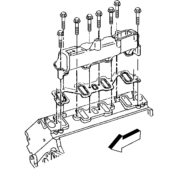
- Remove the intake manifold
bolts.
- Remove the intake manifolds.
- Remove the gaskets.
Intake Manifold Removal C3500HD
Thermostat Housing

- Remove the upper thermostat
housing retaining bolts from the lower thermostat housing.
- Remove the upper thermostat housing (1).
- Remove the thermostats (2) with the seals (3).
- Remove the thermostat seals (3) from the thermostats (2).
- Remove the heater flow control valve.
- Remove the engine coolant temperature (ECT) sensor (6) from the
lower thermostat housing.

- Remove the fuel bleed
valve retaining nut.
- Remove the fuel bleed valve.
- Remove the fuel bleed valve mounting bolt.
- Loosen the thermostat bypass hose retaining clamps.
- Remove the lower thermostat housing retaining bolts.
- Remove the lower thermostat housing.
- Remove the gaskets.
- Remove the thermostat bypass hose.
- Remove the thermostat bypass hose retaining clamps.
- Remove the thermostat bypass hose fitting.
Upper Intake Manifold
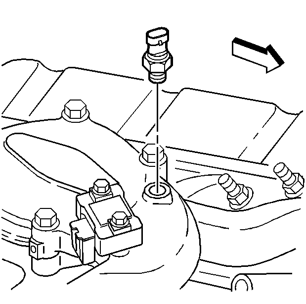
- Disconnect the intake
air temperature (IAT) sensor electrical connector.
- Remove the IAT sensor.
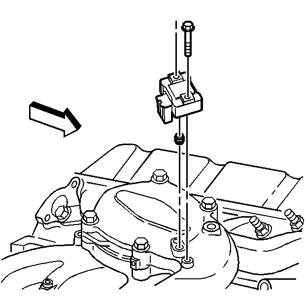
- Disconnect the manifold
absolute pressure (MAP) sensor electrical connector.
- Remove the MAP sensor retaining bolts.
- Remove the MAP sensor.
- Remove the gasket.
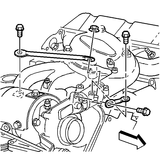
- Remove the turbocharger
short brace retaining bolts.
- Remove the turbocharger short brace.
- Remove the turbocharger long brace retaining bolt.
- Remove the turbocharger long brace retaining nut.
- Remove the turbocharger long brace.
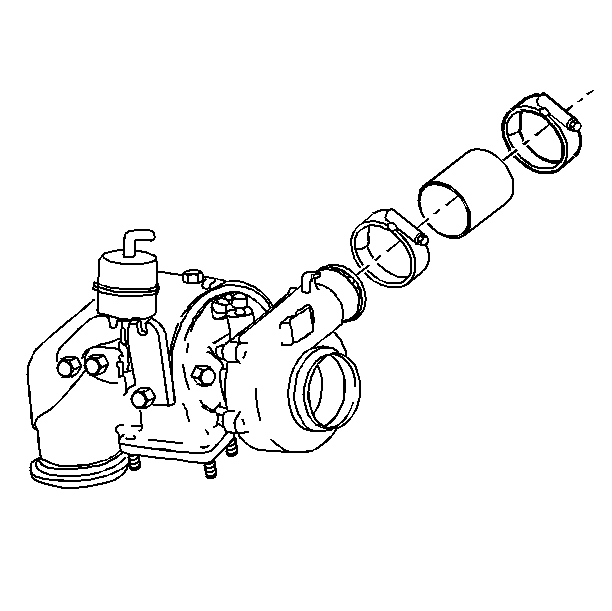
- Loosen the turbocharger
connection hose clamps.
- Loosen the turbocharger connection hose.
| 13.1. | Insert a small flat screwdriver blade between the turbocharger
connection hose and the turbocharger and slide the screwdriver blade along
the surface of the turbocharger until the hose twists freely. |
| 13.2. | Insert a small flat screwdriver blade between the turbocharger
connection hose and the upper intake manifold and slide the screwdriver blade
along the surface of the upper intake manifold until the hose twists freely. |
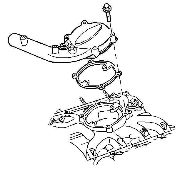
- Remove the upper intake
manifold retaining bolts.
- Remove the upper intake manifold.
- Remove the gasket.
Lower Intake Manifold
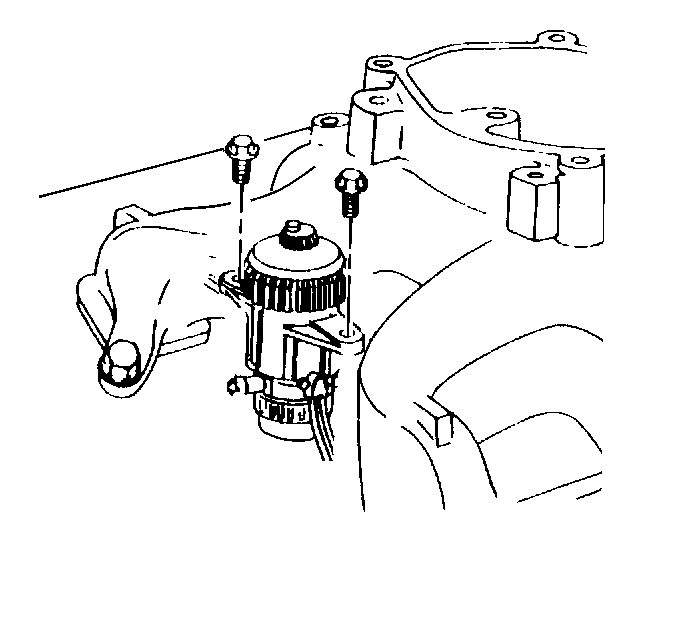
- Remove the fuel manager/filter
assembly retaining bolts.
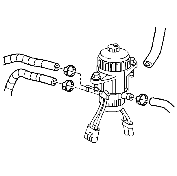
- Loosen the fuel hose clamps
at the fuel filter assembly.
- Remove the fuel hoses from the fuel filter assembly.
- Disconnect the fuel manager/filter electrical connector.
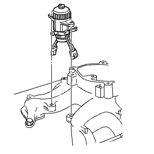
- Remove the fuel filter
assembly.
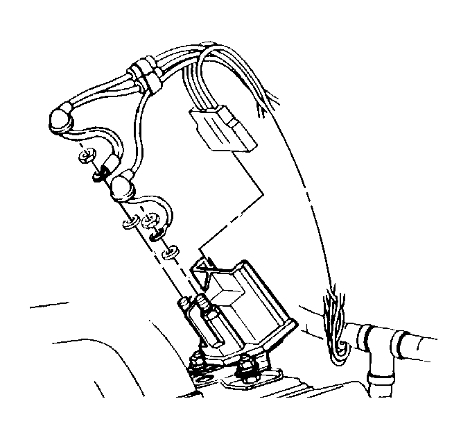
- Disconnect the glow plug
relay electrical connector.
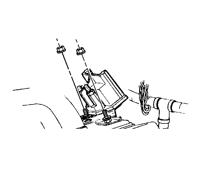
- Remove the glow plug relay
retaining nuts.
- Remove the glow plug relay.
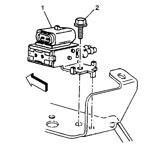
- Disconnect the vacuum harness hose connectors.
- Remove the vacuum harness.
- Remove the vacuum solenoid retaining bolt(s) (2).
- Remove the vacuum solenoid(s) (1).
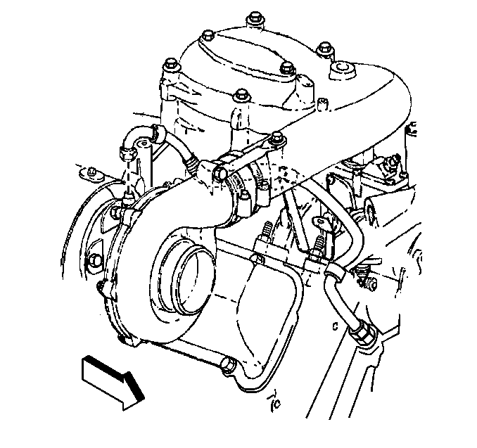
- Remove the turbocharger
oil feed line mounting bracket retaining nut.
- Remove the turbocharger oil feed line mounting bracket. Gently
pull the bracket from the turbocharger oil feed line at a 45 degree
angle to separate.
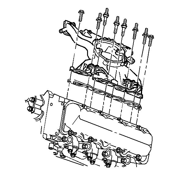
- Remove the lower intake
manifold bolts.
- Remove the lower intake manifold.
- Remove the gaskets.


