Fuel Injection Pump Replacement for Chevrolet Chevy C Cab/Chassis HD (GMT 400) 2002
Tools Required
J 41089 Injection Pump Wrench

Removal Procedure
- Remove the negative battery cables.
- Remove the intake manifold. Refer to Upper Intake Manifold Replacement and Lower Intake Manifold Replacement in Engine Mechanical - 6.5L.
- Remove the injection lines. Refer to Fuel Injection Line Replacement .
- Remove the fuel inlet line from the injection pump.
- Remove all necessary harness connectors and hoses from the injection pump.
- Remove the fuel return line at the top of the injection pump.
- Remove the oil fill tube.
- Remove the grommet for the oil filler tube.
- Rotate the engine to gain access to the bolts (1) that hold the driven gear to the injection pump. Access is gained through the oil filler neck hole.
- Remove the driven gear bolts.
- Remove the injection pump flange nuts. Use the J 41089 injection pump wrench.
- Remove the injection pump.
- Cap all open lines and nozzles.
- Remove the flange gasket.
Caution: Unless directed otherwise, the ignition and start switch must be in the OFF or LOCK position, and all electrical loads must be OFF before servicing any electrical component. Disconnect the negative battery cable to prevent an electrical spark should a tool or equipment come in contact with an exposed electrical terminal. Failure to follow these precautions may result in personal injury and/or damage to the vehicle or its components.
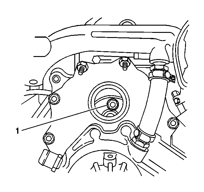
Important : Never engage the starter motor to rotate the engine when the injection pump is removed as severe engine damage will occur. With the injection pump removed the pump driven gear could jam in the front housing by engaging the starter motor, resulting in a sheared crankshaft or camshaft gear key and possible valve train damage. Always bar the engine over by hand to avoid internal engine damage.
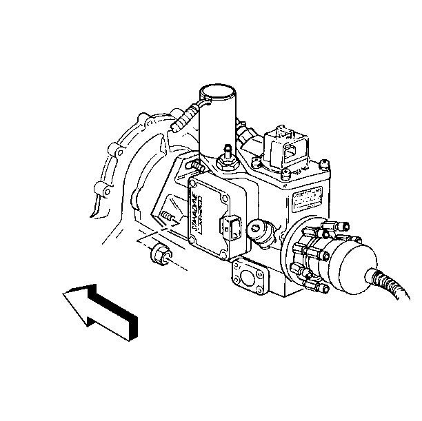
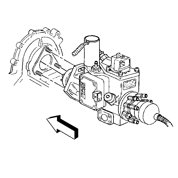
Installation Procedure
- Install the new flange gasket on the injection pump .
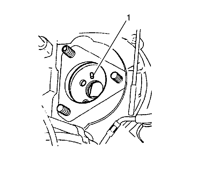
- Adjust the locating stud (1) to the proper position to match with the slotted/elongated hole in the driven gear.
- Install the injection pump making sure the locating stud is positioned within the slotted/elongated hole (1) in the driven gear.
- Install the injection pump flange nuts.
- Install the driven gear bolts (1).
- Install the grommet for the oil filler tube.
- Install the oil filler tube.
- Install the fuel feed line at the injection pump.
- Install the fuel return line to the top of the injection pump.
- Install all necessary harnesses and connectors.
- Install the injection lines. Refer to the tags on lines. Refer to Fuel Injection Line Replacement .
- Install the intake manifold. Refer to Upper Intake Manifold Replacement and Lower Intake Manifold Replacement in Engine Mechanical - 6.5L.
- Install the negative battery cables.
- Adjust the injection timing. Refer to Fuel Injection Pump Timing Adjustment .
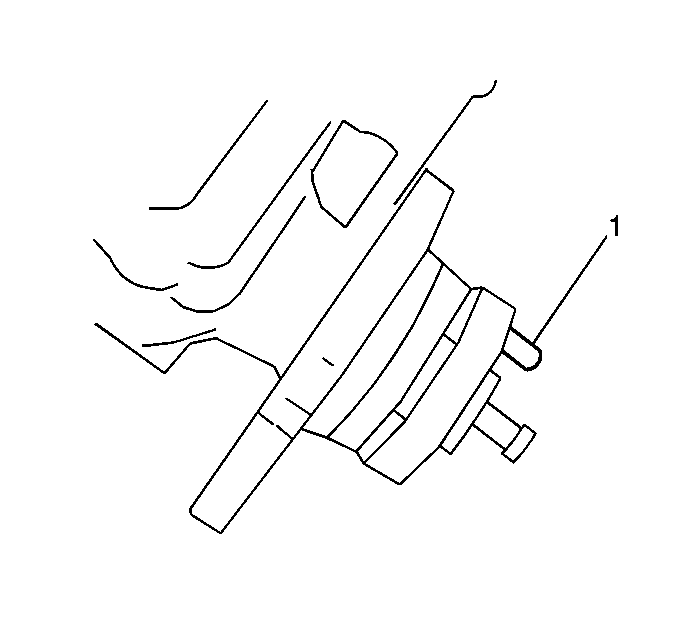
Important: Be sure the locating stud (1) on the injection pump hub goes into the slotted/elongated hole in the driven gear.
Notice: Use the correct fastener in the correct location. Replacement fasteners must be the correct part number for that application. Fasteners requiring replacement or fasteners requiring the use of thread locking compound or sealant are identified in the service procedure. Do not use paints, lubricants, or corrosion inhibitors on fasteners or fastener joint surfaces unless specified. These coatings affect fastener torque and joint clamping force and may damage the fastener. Use the correct tightening sequence and specifications when installing fasteners in order to avoid damage to parts and systems.
Tighten
Tighten nuts to 40 N·m (30 lb ft).
Important: All the driven gear bolts should not be torqued until all the bolts are installed. This will allow for the proper alignment of all the bolt holes.
Tighten
Tighten the bolts to 25 N·m (18 lb ft).
