GM Service Manual Online
For 1990-2009 cars only
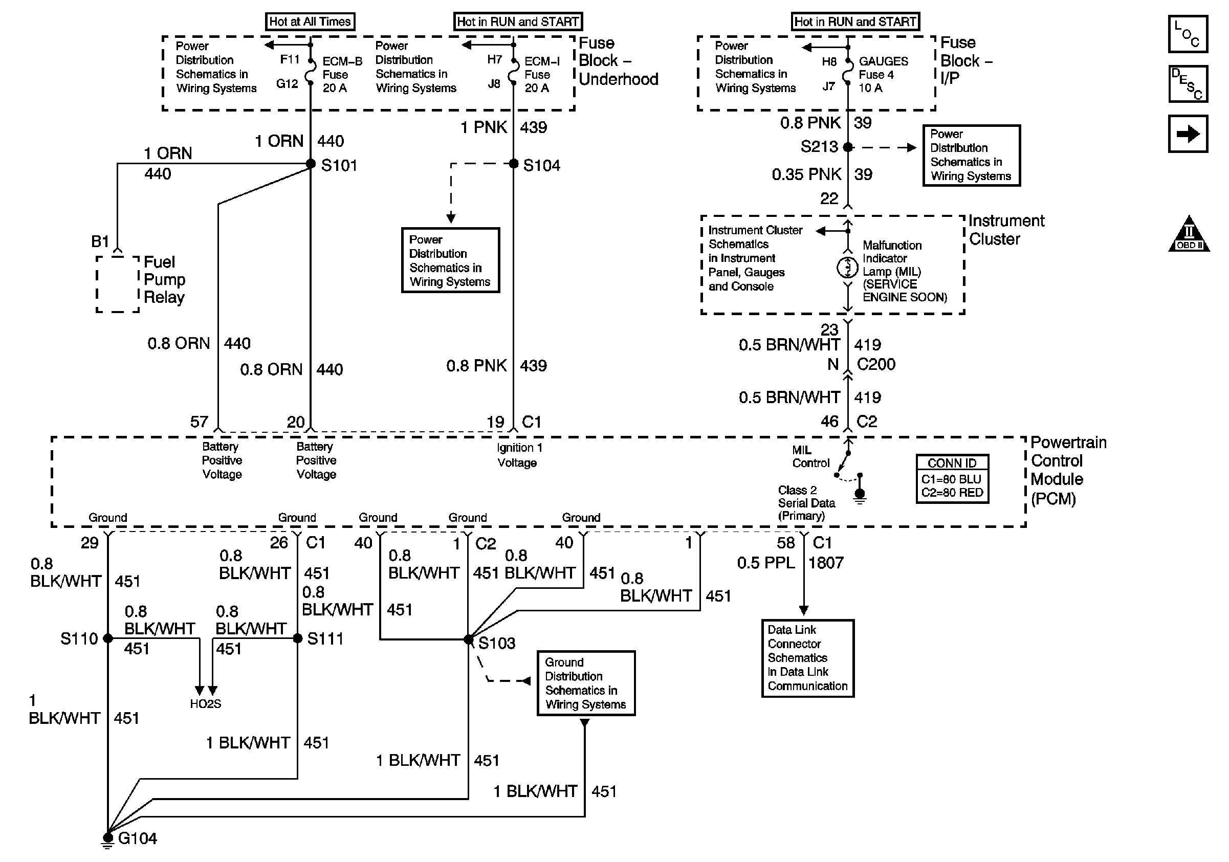
Figure 1:

PCM Power, Grounding, DLC, and MIL


Object Number: 786838  Size: FS
Master Electrical Component List
Powertrain Control Module Description
5 Volt and Low Reference Busses
OBD II Symbol Description Notice
ECM-B, Horn
IGN A Fuse and Ignition Switch
ECM-I Fuse, 1 of 2 Fuel Injectors
IGN A Fuse and Ignition Switch
G203
Gages Fuse and Turn-B/U Fuse
G203
Data Link Connector (DLC) Schematics
G104, L18, 1 of 2, All Except HO2S Circuit
HO2S Circuit
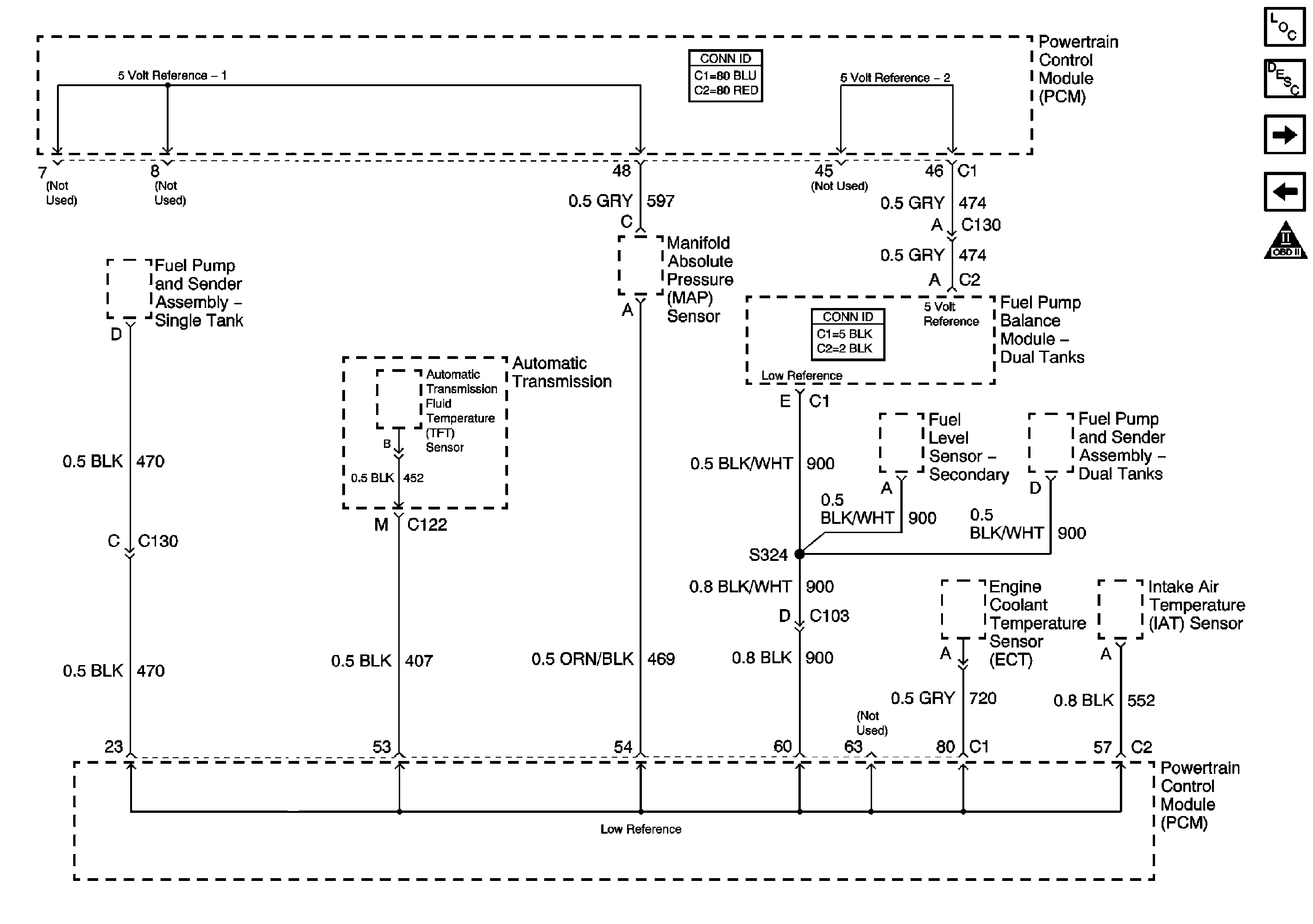
Figure 2:

5 Volt and Low Reference Busses


Object Number: 1455112  Size: FS
Master Electrical Component List
Powertrain Control Module Description
MAP, ECT, VSS Circuit, and IAT/MAF
PCM Power, Grounding, DLC, and MIL
OBD II Symbol Description Notice
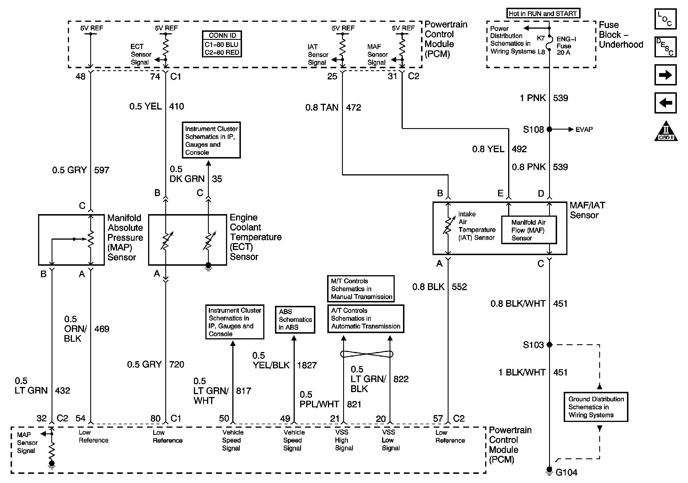
Figure 3:

MAP, ECT, VSS Circuit, and IAT/MAF


Object Number: 786841  Size: FS
Master Electrical Component List
Powertrain Control Module Description
HO2S Circuit
5 Volt and Low Reference Busses
OBD II Symbol Description Notice
IGN A Fuse and Ignition Switch
G104, L18, 1 of 2, All Except HO2S Circuit
L18 Internal Switches, TFT, PC Solenoid Valve, and Shaft Speed Sensors
Speedometer, Tachometer, and Fuel Gage
Oil Pressure, Coolant Temperature, and Voltage Gages, Battery, and Check Gages Indicators
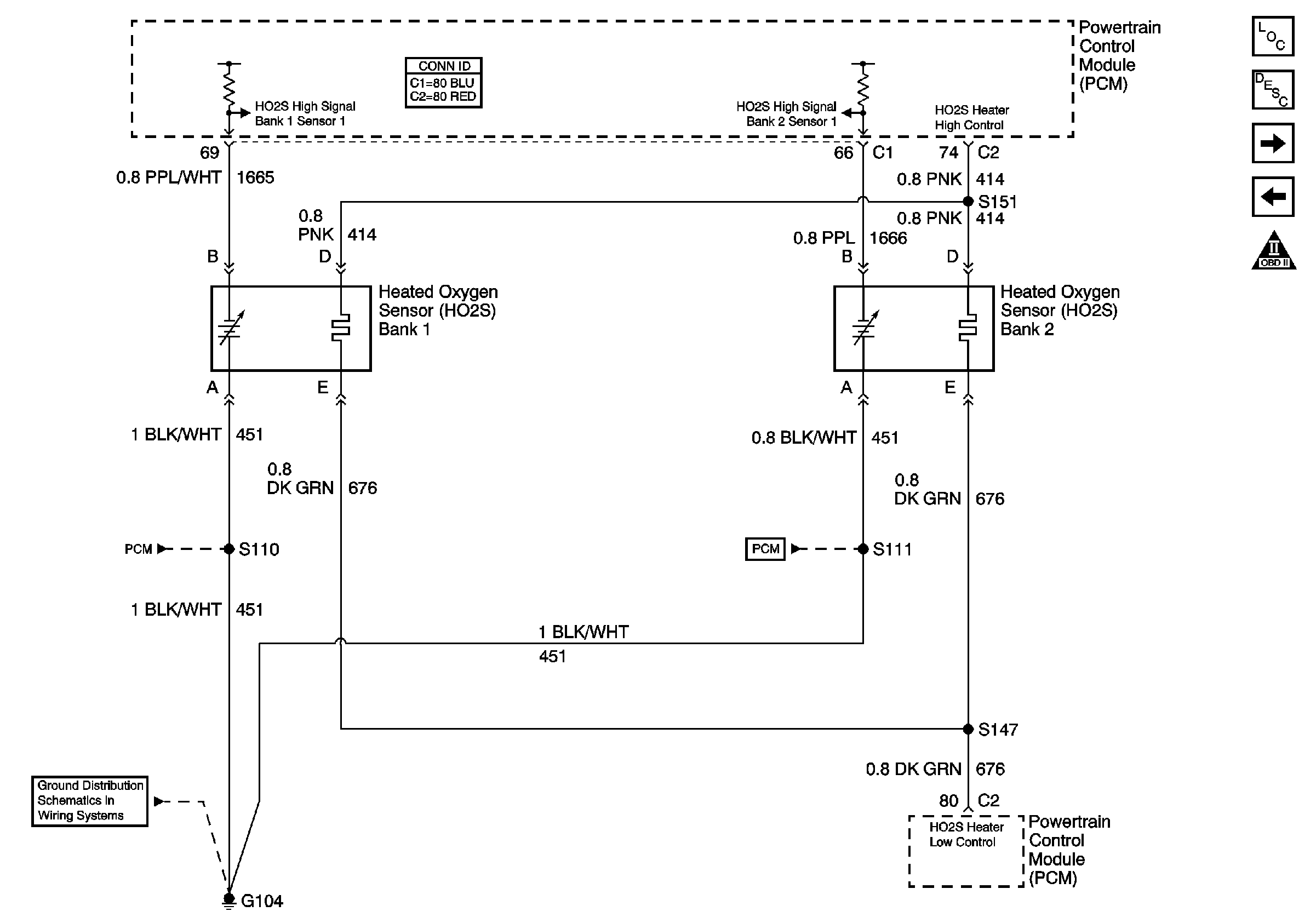
Figure 4:

HO2S Circuit


Object Number: 647035  Size: FS
Master Electrical Component List
Powertrain Control Module Description
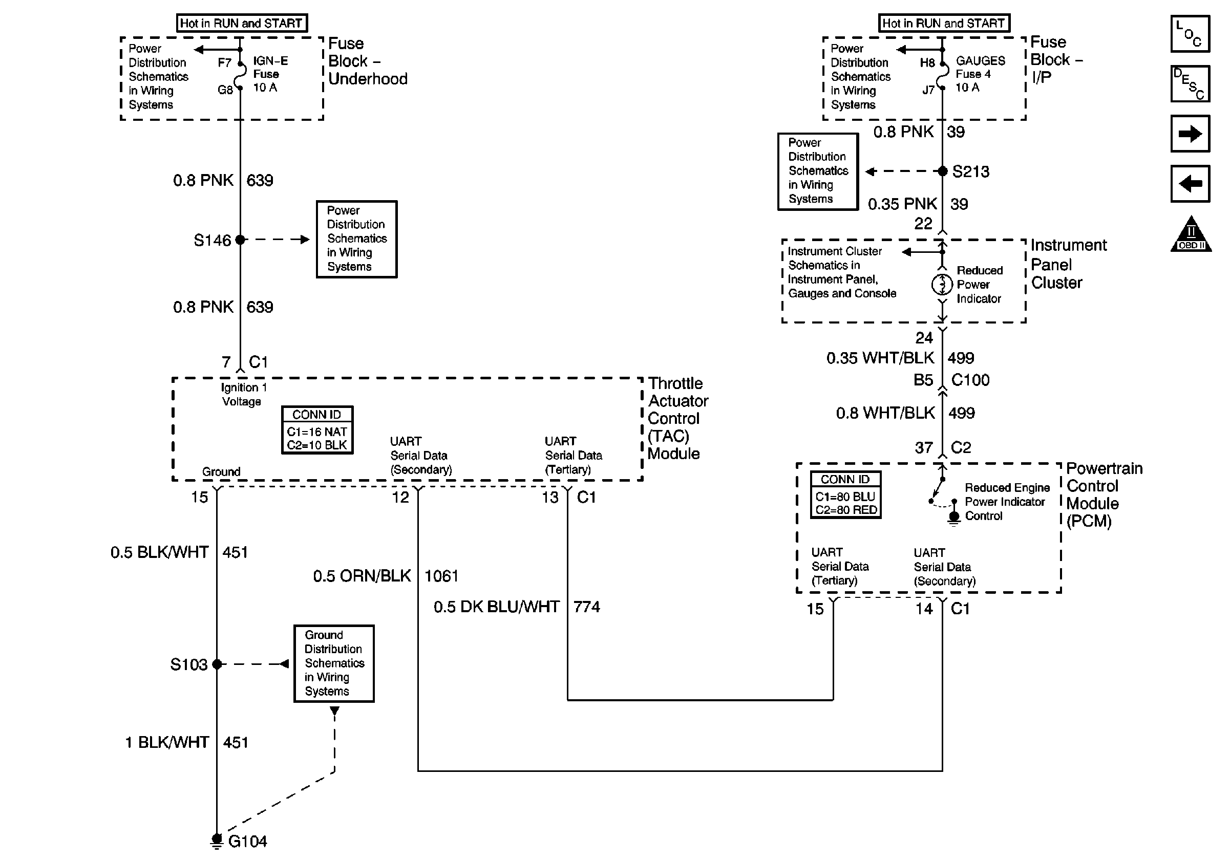
2004 CK 400 Mexico TAC Power, Grounding, Data Circuits, and Indicator Control
MAP, ECT, VSS Circuit, and IAT/MAF
OBD II Symbol Description Notice
PCM Power, Grounding, DLC, and MIL
G104, L18, 1 of 2, All Except HO2S Circuit
PCM Power, Grounding, DLC, and MIL
Figure 5:

TAC Power, Grounding, Data Circuits, and Indicator Control


Object Number: 647040  Size: FS
Master Electrical Component List
Throttle Actuator Control (TAC) System Description
2004 CK 400 Mexico Throttle Control Circuits
HO2S Circuit
OBD II Symbol Description Notice
IGN A Fuse and Ignition Switch
ENGI and IGN-E Fuse - L18
G104, L18, 1 of 2, All Except HO2S Circuit
IGN A Fuse and Ignition Switch
Gages Fuse and Turn-B/U Fuse
G203
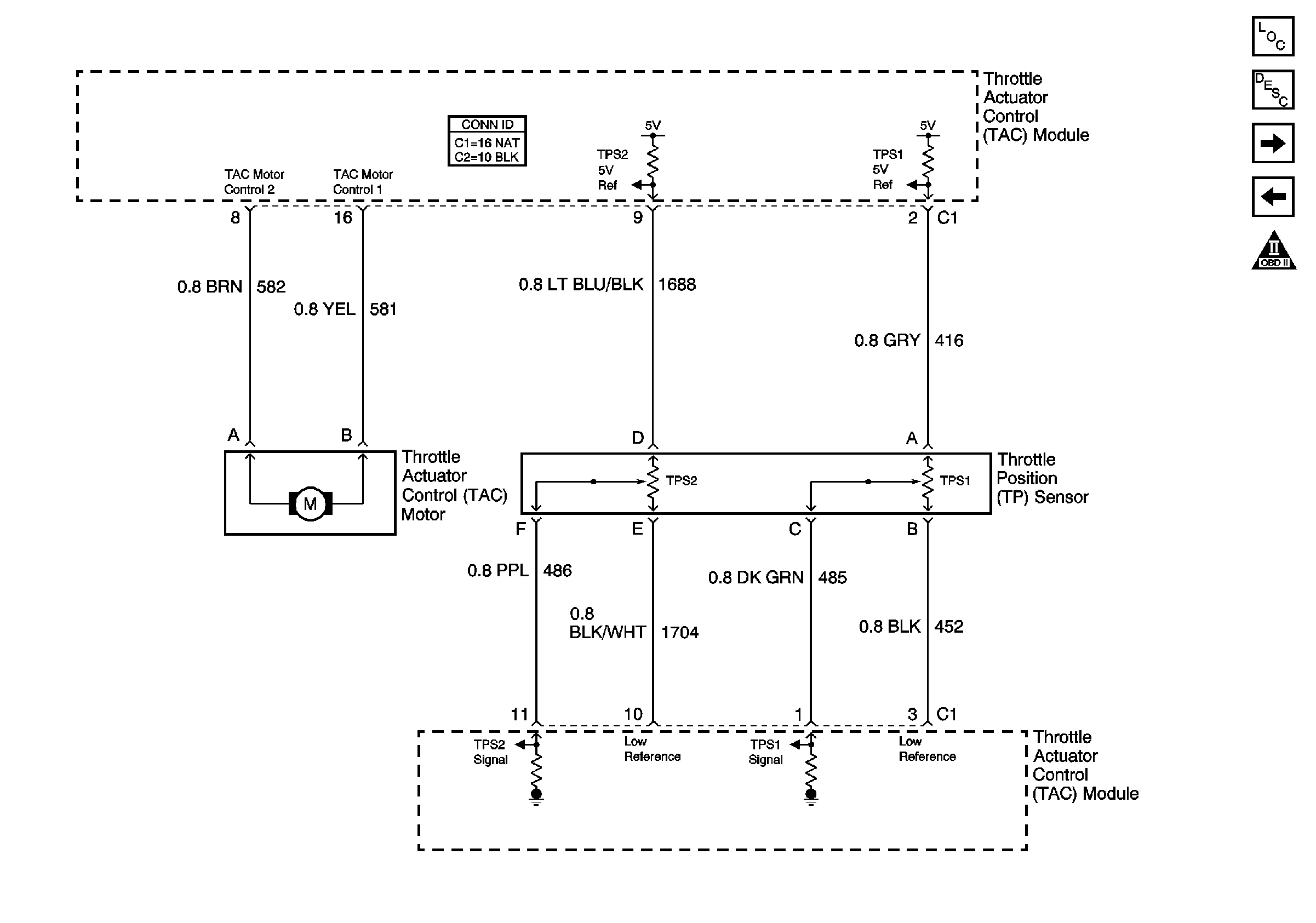
Figure 6:

Throttle Control Circuits


Object Number: 647042  Size: FS
Master Electrical Component List
Throttle Actuator Control (TAC) System Description
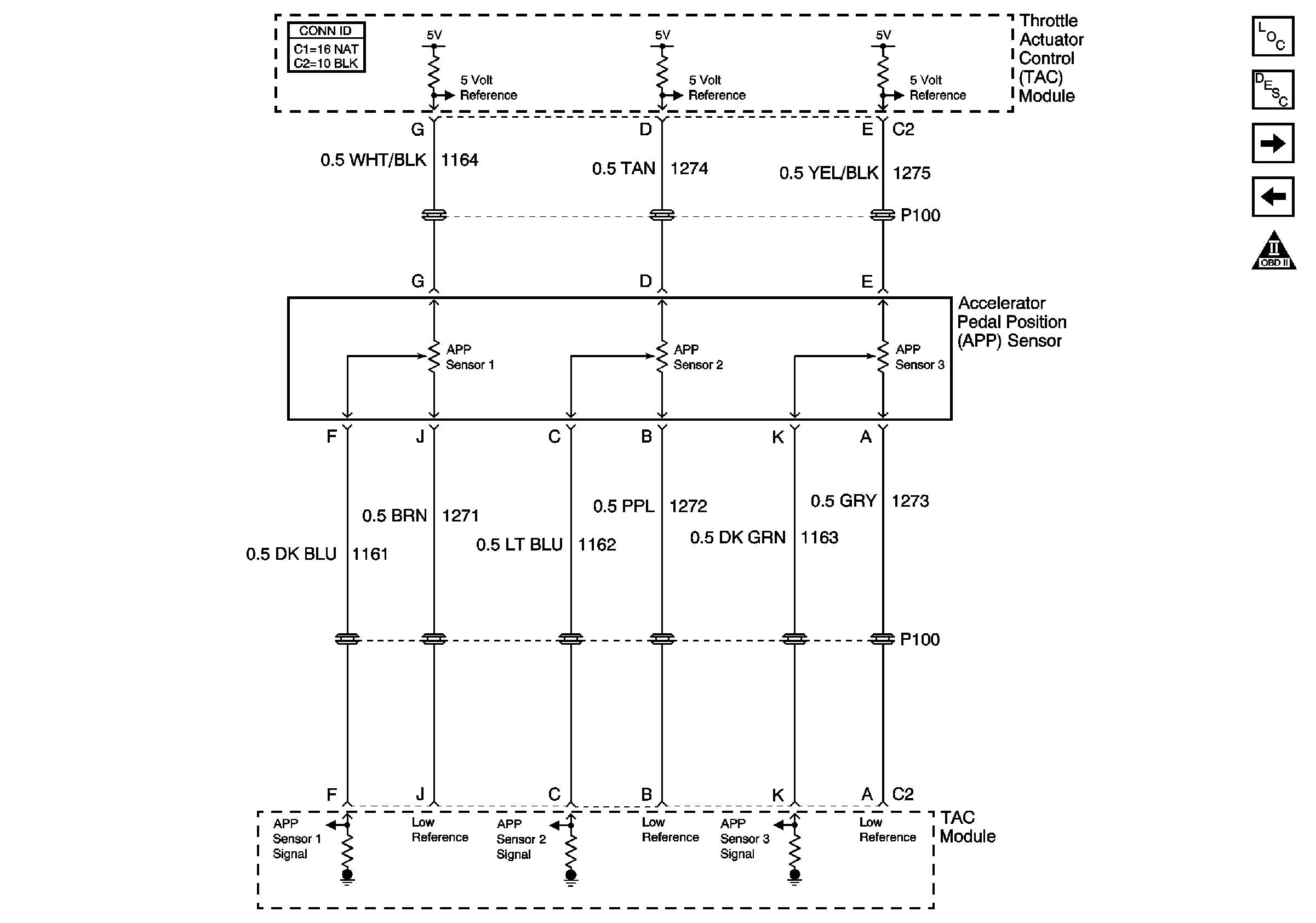
Accelerator Pedal Position Sensor Circuits
2004 CK 400 Mexico TAC Power, Grounding, Data Circuits, and Indicator Control
OBD II Symbol Description Notice
Figure 7:

Accelerator Pedal Position Sensor Circuits


Object Number: 647044  Size: FS
Master Electrical Component List
Throttle Actuator Control (TAC) System Description
TAC Cruise Control Inputs
2004 CK 400 Mexico Throttle Control Circuits
OBD II Symbol Description Notice
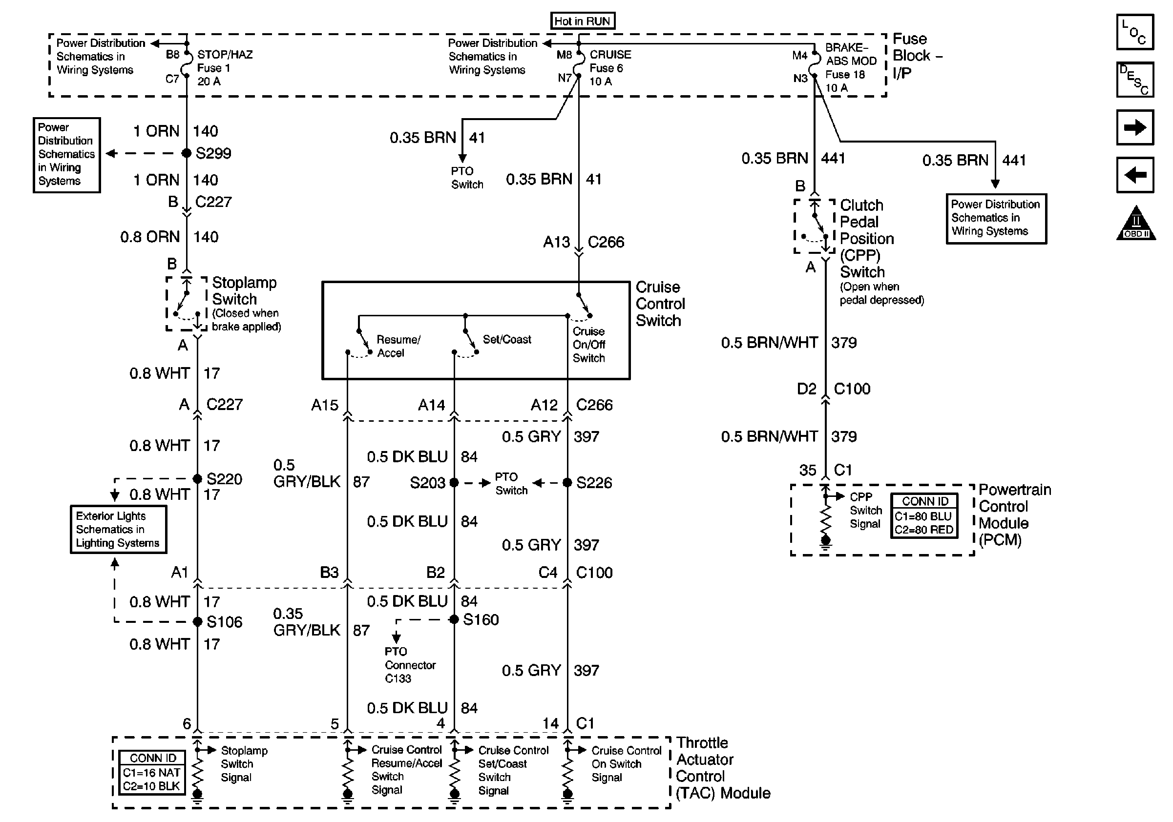
Figure 8:

TAC Cruise Control Inputs


Object Number: 647045  Size: FS
Master Electrical Component List
Throttle Actuator Control (TAC) System Description
PTO Control Provisions
Accelerator Pedal Position Sensor Circuits
OBD II Symbol Description Notice
Stop/Haz, Radio Batt, Aux Pwr, and Cig Ltr Fuses
Lighting and Battery Fuses
ABS, Blower, Stop-Haz, and IGN B Fuses, and Igntion Switch
PTO Control Provisions
Brake, Curise, SEO TP-2, and Htr-Fuses
PTO Control Provisions
Stop and Turn/Hazard Lamps Control
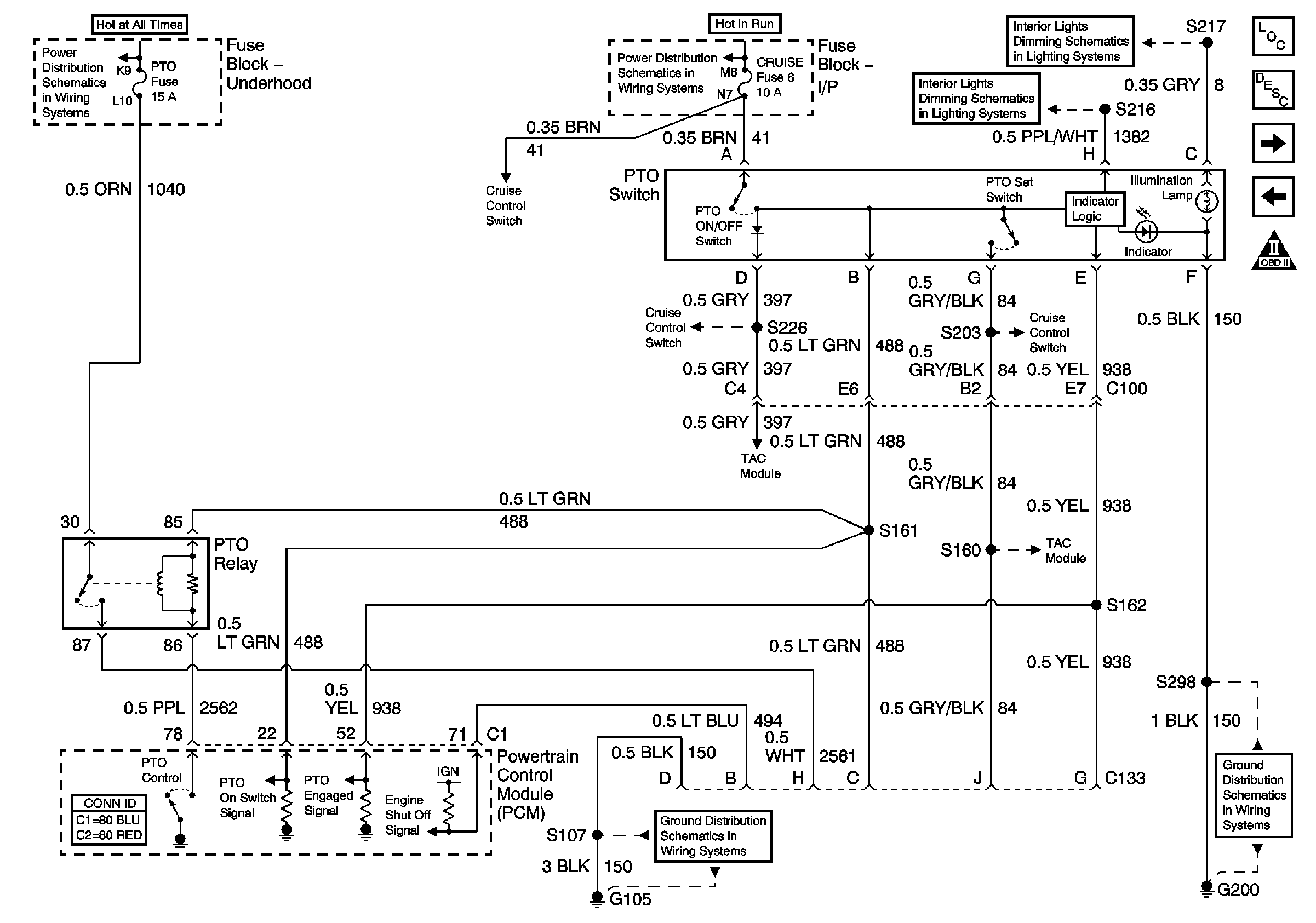
Figure 9:

PTO Control Provisions


Object Number: 647046  Size: FS
Master Electrical Component List
Ignition Control, Bank 1 (Left Side)
TAC Cruise Control Inputs
OBD II Symbol Description Notice
Battery and Underhood Fuse Block
TAC Cruise Control Inputs
ABS, Blower, Stop-Haz, and IGN B Fuses, and Igntion Switch
Interior Dimming Schematics
TAC Cruise Control Inputs
G200
TAC Cruise Control Inputs
G105, L18, 1 of 2, All Except Ignition Coils
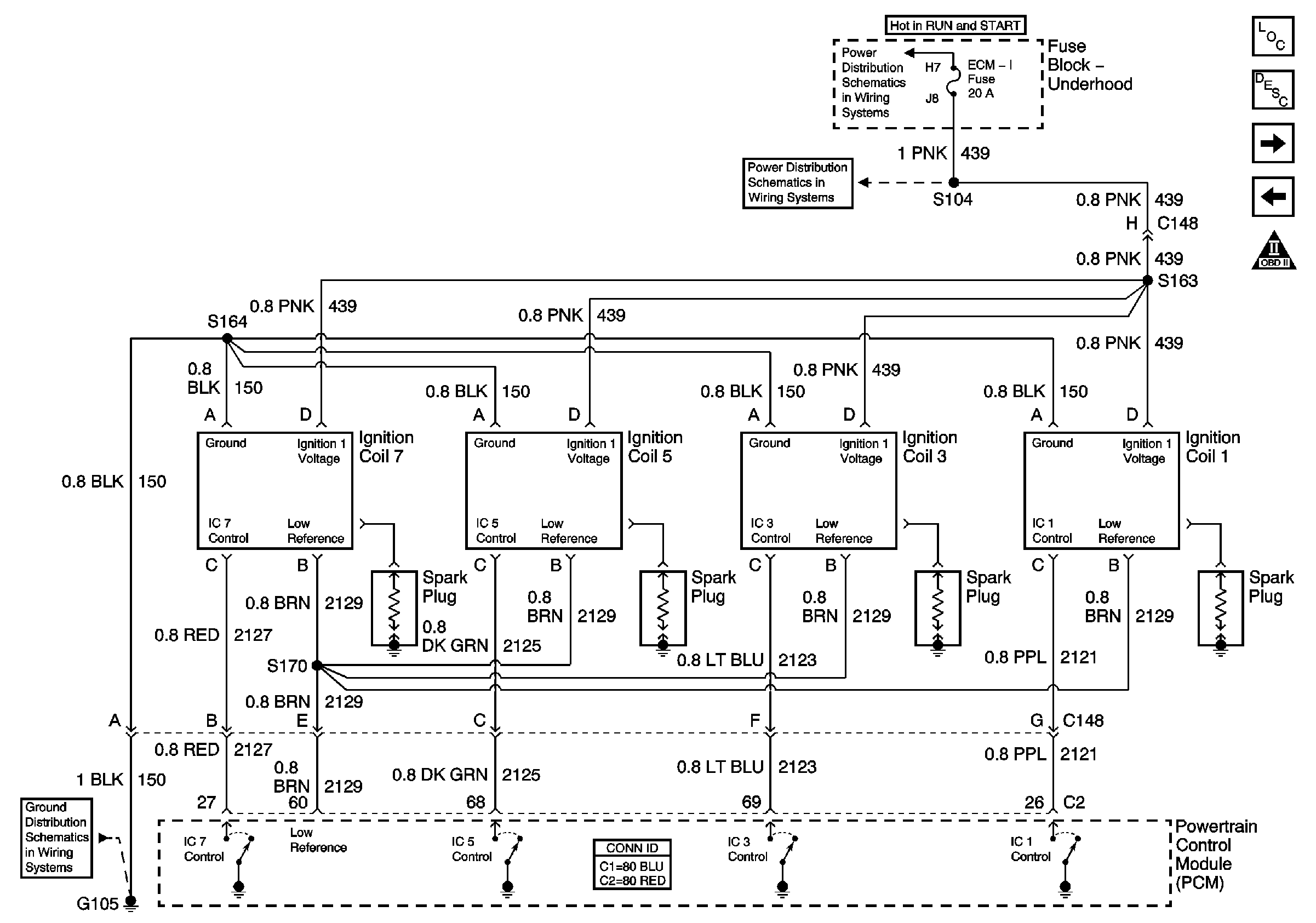
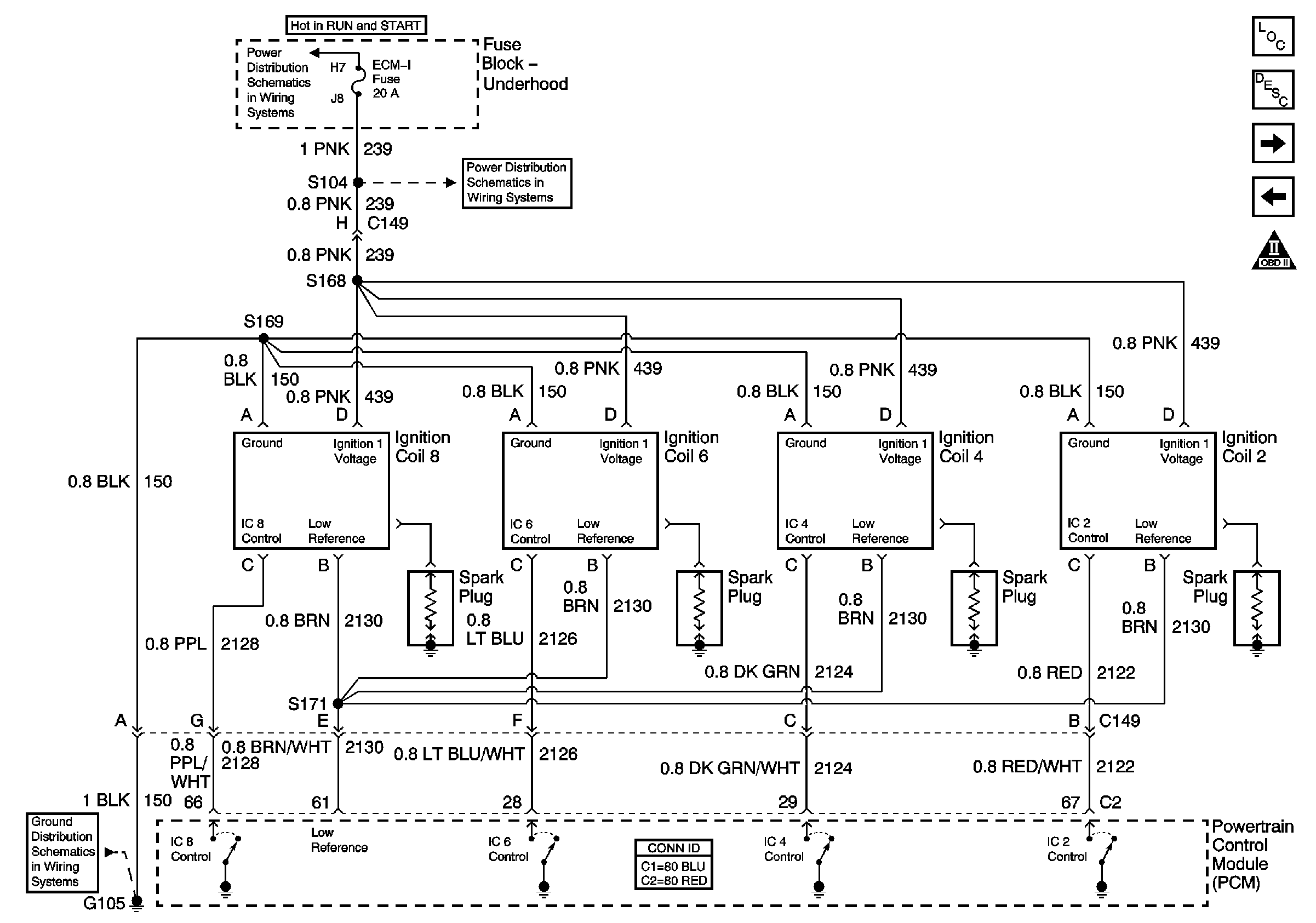
Figure 10:

Ignition Control, Bank 1 (Left Side)


Object Number: 647023  Size: FS
Master Electrical Component List
Electronic Ignition (EI) System Description
Ignition Control, Bank 1 (Right Side)
PTO Control Provisions
OBD II Symbol Description Notice
IGN A Fuse and Ignition Switch
ECM-I Fuse, 2 of 2 Ignition Coils
G105, L18, 2 of 2, Ignition Coils
Figure 11:

Ignition Control, Bank 2 (Right Side)


Object Number: 647026  Size: FS
Master Electrical Component List
Electronic Ignition (EI) System Description
CMP, CKP, and KS
Ignition Control, Bank 1 (Left Side)
OBD II Symbol Description Notice
IGN A Fuse and Ignition Switch
ECM-I Fuse, 2 of 2 Ignition Coils
G105, L18, 2 of 2, Ignition Coils
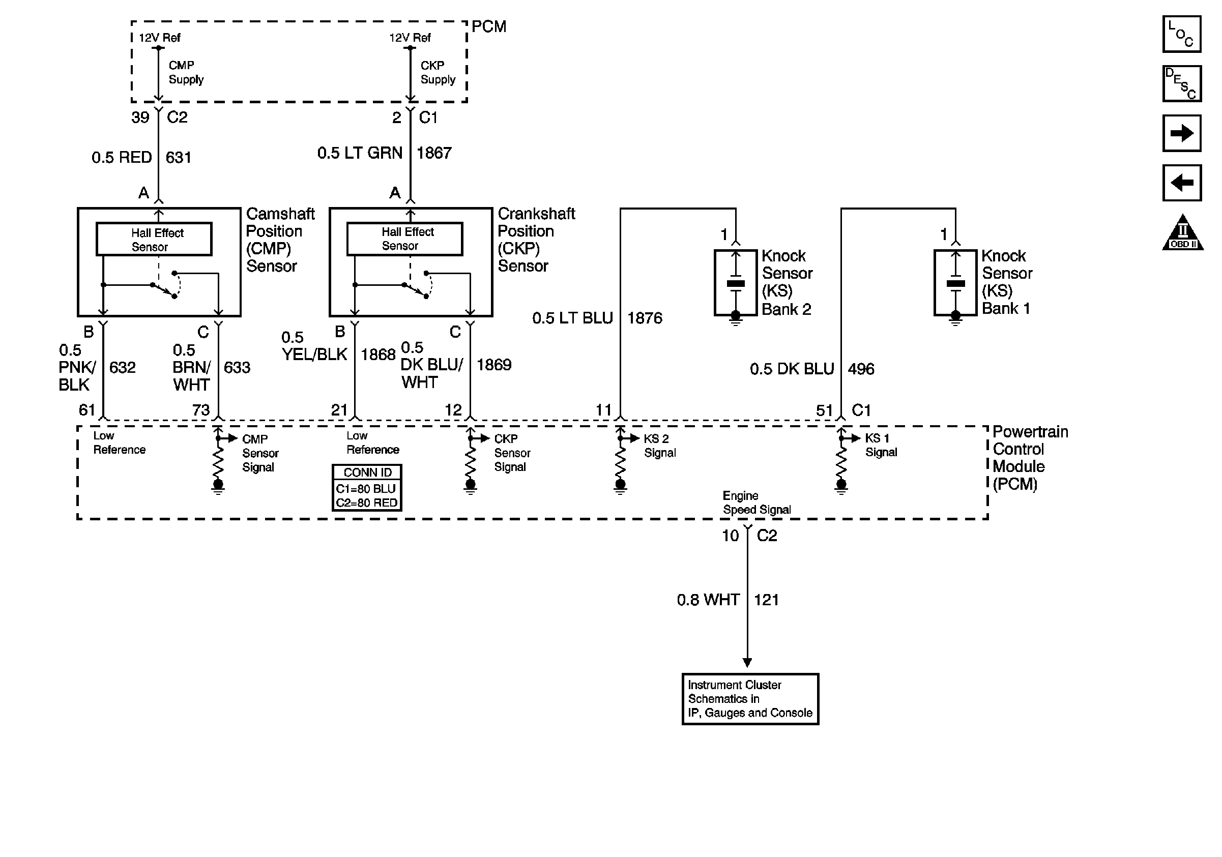
Figure 12:

CMP, CKP, and KS


Object Number: 786842  Size: FS
Master Electrical Component List
Knock Sensor (KS) System Description
Fuel Pump Controls, Single Tank
Ignition Control, Bank 1 (Right Side)
OBD II Symbol Description Notice
G112, Lights, Right Side
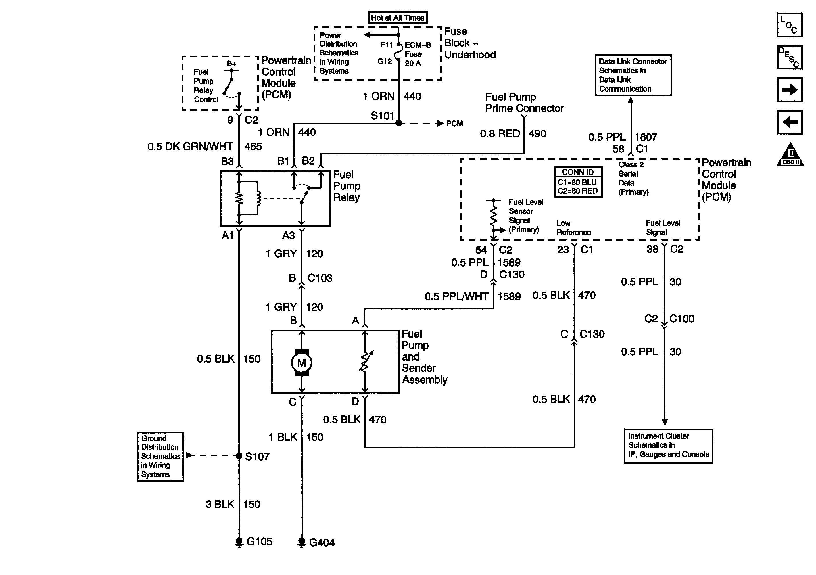
Figure 13:

Fuel Pump Controls, Single Tank


Object Number: 1554535  Size: FS
Master Electrical Component List
Fuel System Description
Fuel Pump Controls, Dual Tanks
CMP, CKP, and KS
OBD II Symbol Description Notice
Battery and Underhood Fuse Block
PCM Power, Grounding, DLC, and MIL
Theft Deterrent System Schematics
Data Link Connector (DLC) Schematics
Speedometer, Tachometer, and Fuel Gage
G105, L18, 1 of 2, All Except Ignition Coils
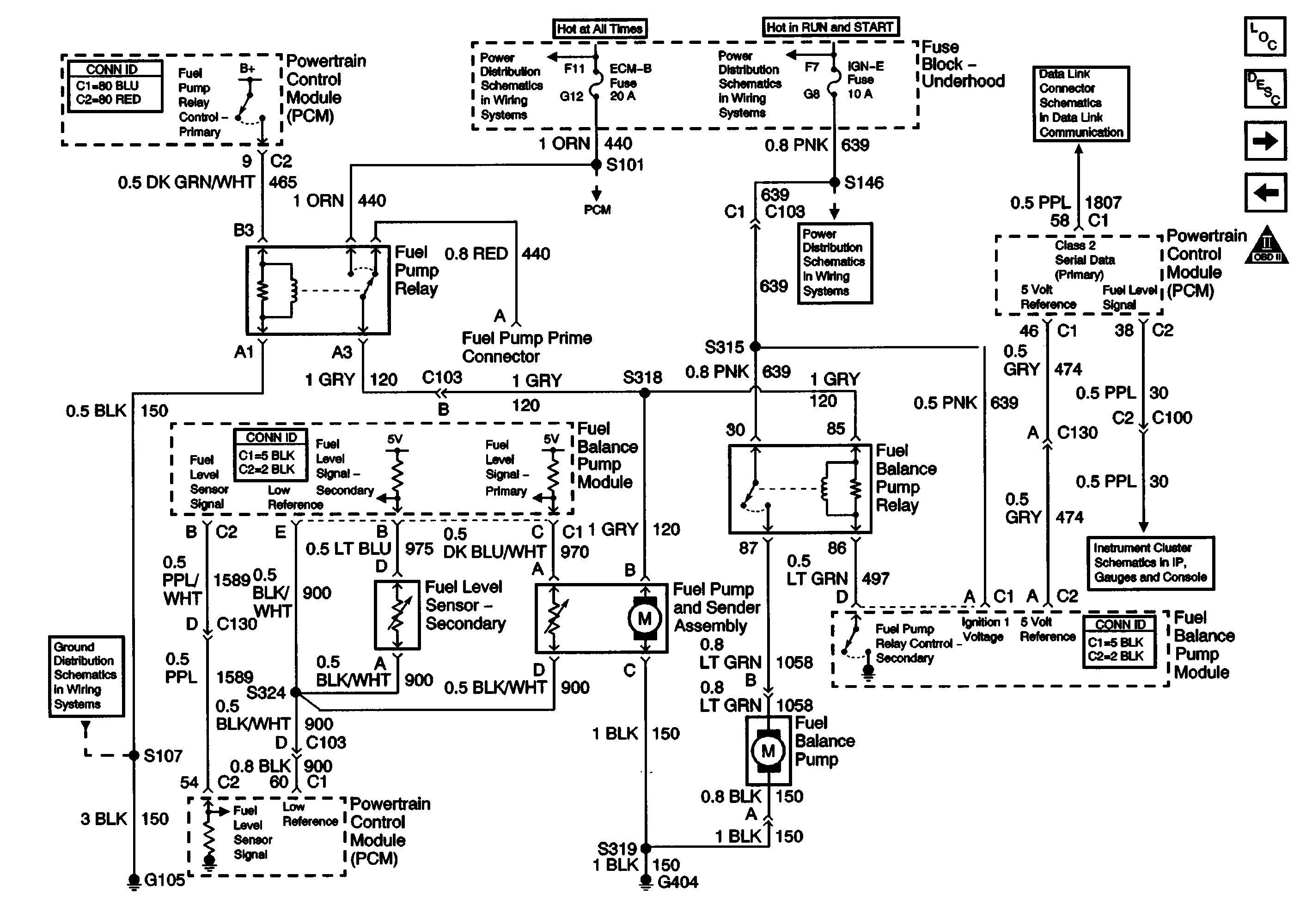
Figure 14:

Fuel Pump Controls, Dual Tanks


Object Number: 1554536  Size: FS
Master Electrical Component List
Fuel System Description
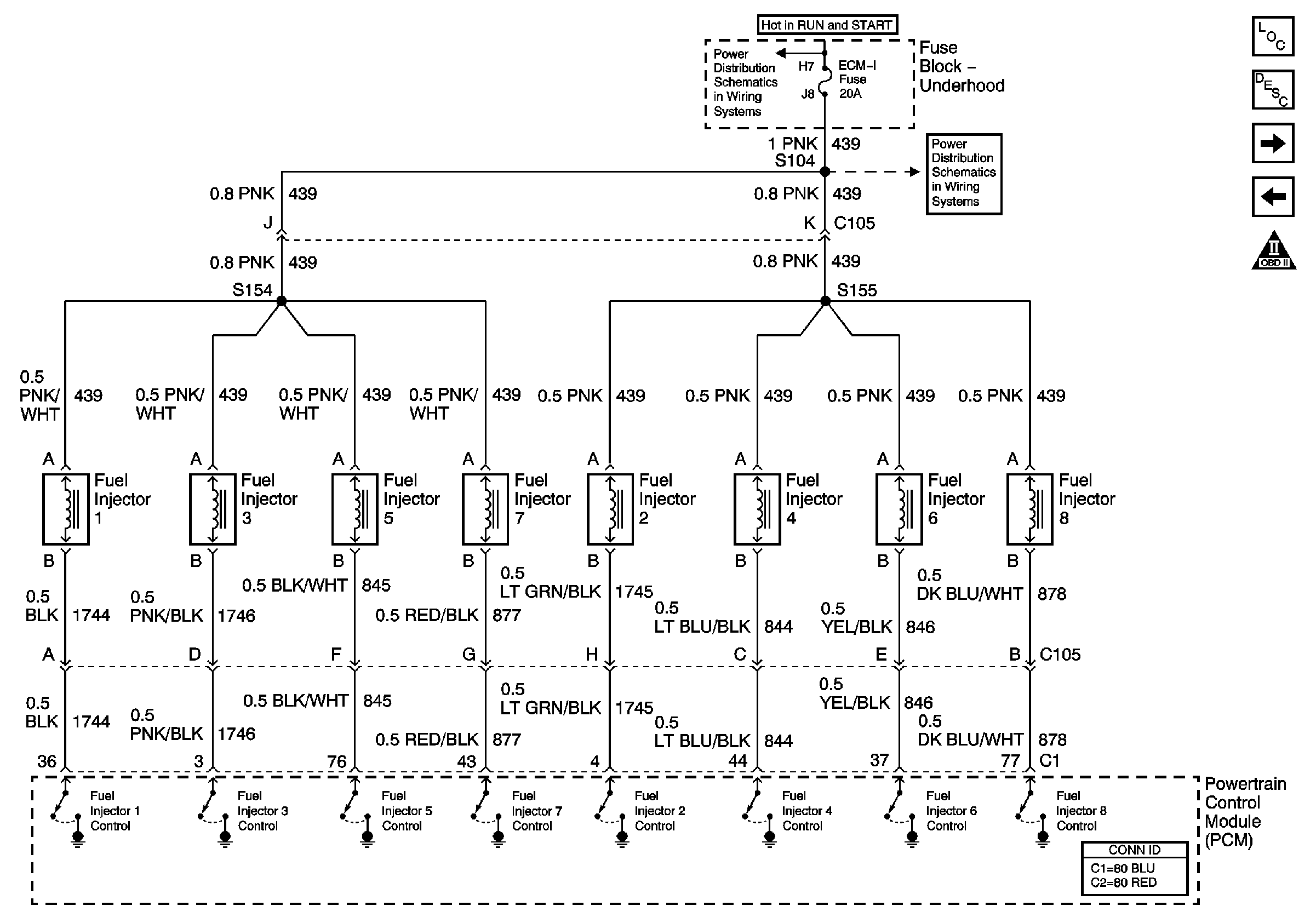
Fuel Injector Controls
Fuel Pump Controls, Single Tank
OBD II Symbol Description Notice
Battery and Underhood Fuse Block
PCM Power, Grounding, DLC, and MIL
IGN A Fuse and Ignition Switch
ENGI and IGN-E Fuse - L18
Theft Deterrent System Schematics
Data Link Connector (DLC) Schematics
Speedometer, Tachometer, and Fuel Gage
G105, L18, 1 of 2, All Except Ignition Coils
Figure 15:

Fuel Injector Controls


Object Number: 647029  Size: FS
Master Electrical Component List
Fuel System Description
Fuel Pump Controls, Dual Tanks
OBD II Symbol Description Notice
IGN A Fuse and Ignition Switch
ECM-I Fuse, 1 of 2 Fuel Injectors
Figure 16:

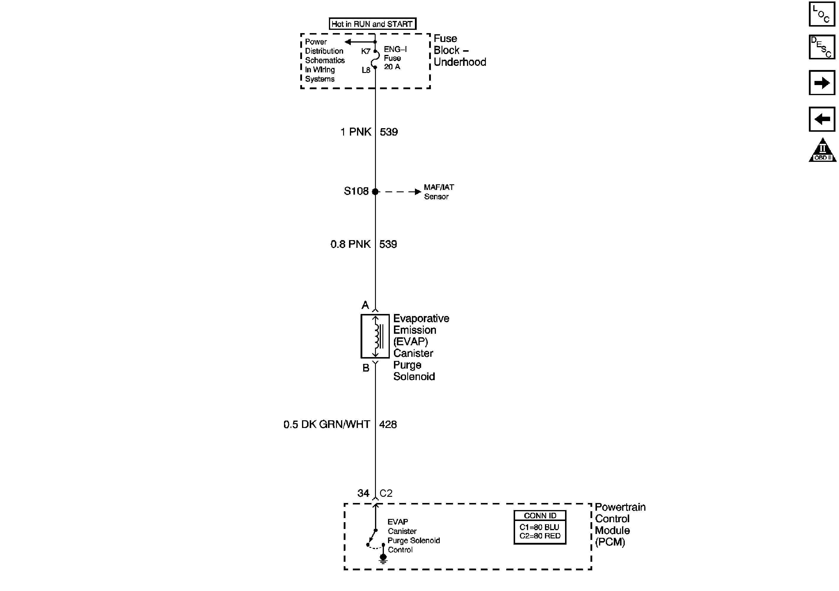
EVAP and EGR


Object Number: 1455116  Size: FS
Master Electrical Component List
Evaporative Emission Control System Description with FE9 and above 8600 GVW
A/T TCC/Stop Lamp Switch, Shift Solenoids
Fuel Injector Controls
OBD II Symbol Description Notice
IGN A Fuse and Ignition Switch
MAP, ECT, VSS Circuit, and IAT/MAF
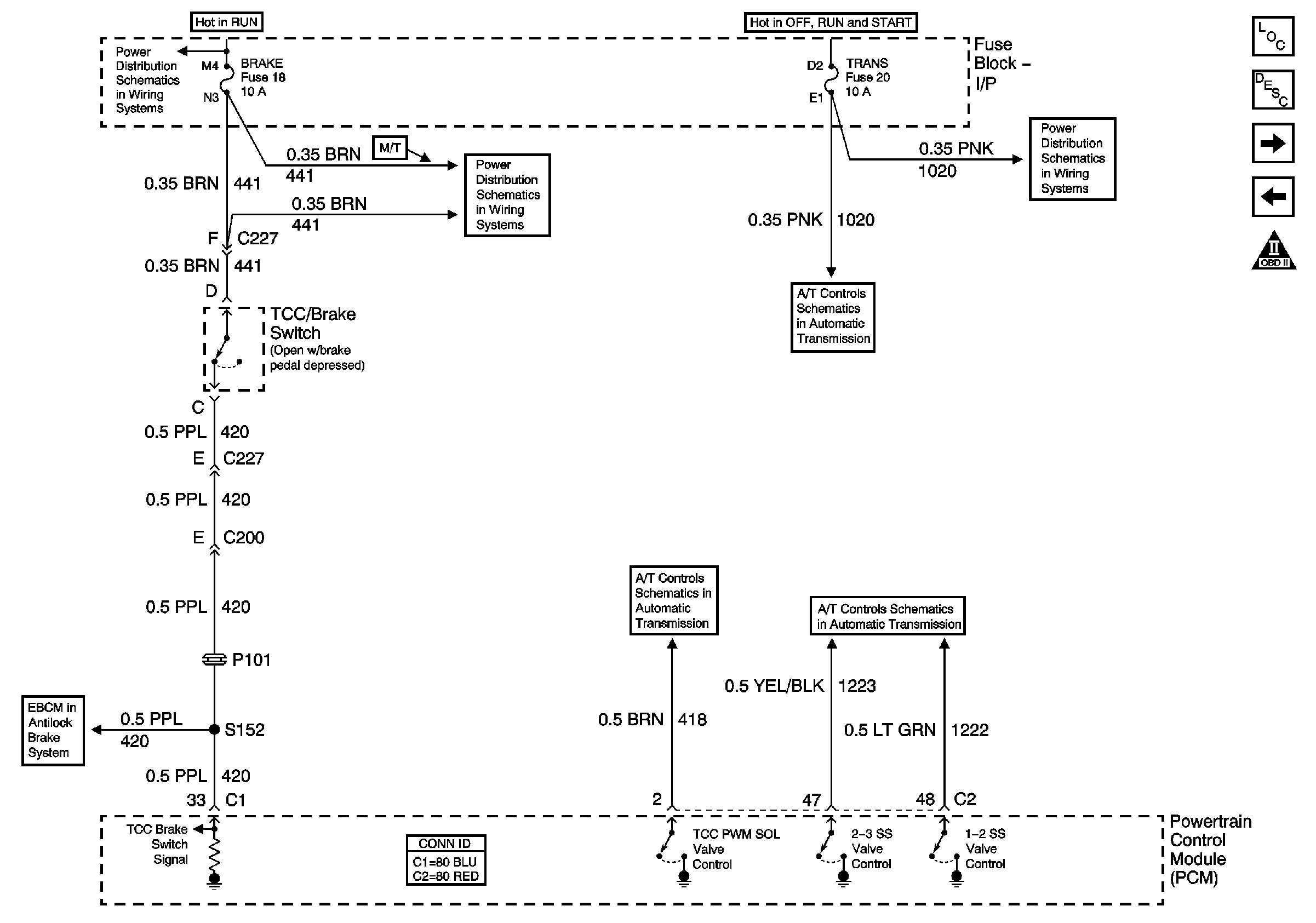
Figure 17:

A/T TCC/Stop Lamp Switch, Shift Solenoids


Object Number: 786846  Size: FS
Master Electrical Component List
Electronic Component Description
EVAP
OBD II Symbol Description Notice
ABS, Blower, Stop-Haz, and IGN B Fuses, and Igntion Switch
Brake, Curise, SEO TP-2, and Htr-Fuses
IGN A Fuse and Ignition Switch
L18 TCC/Stoplamp Switch and Shift Solenoids
Pwr Wdos Circuit Breaker, Wiper, Radio, Clock, and Trans Fuses
L18 TCC/Stoplamp Switch and Shift Solenoids
EBCM Stop Lamp Switch and Wheel Speed Inputs
Figure 18:

A/T Internal Switches, TFT, PC Solenoid Valve
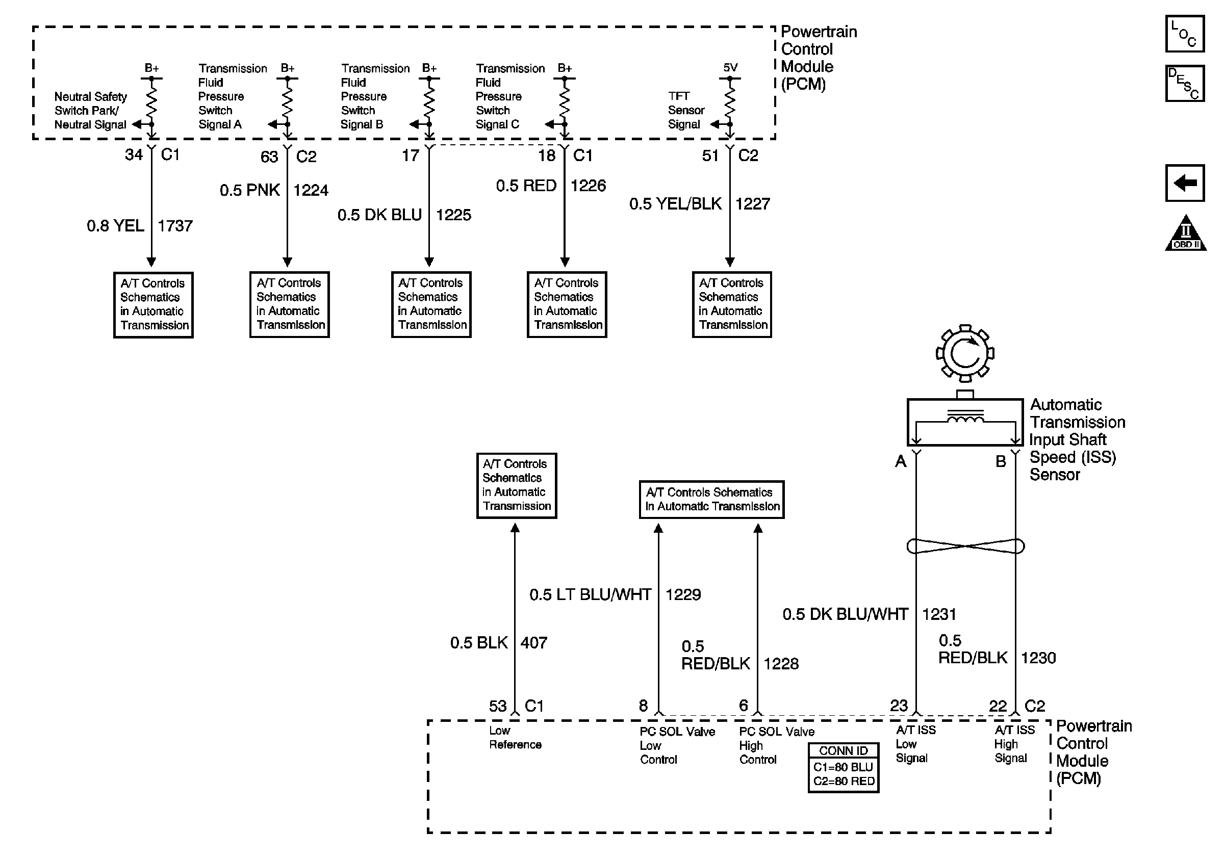

Object Number: 786848  Size: FS
Master Electrical Component List
Electronic Component Description
A/T TCC/Stop Lamp Switch, Shift Solenoids
OBD II Symbol Description Notice
L18 Internal Switches, TFT, PC Solenoid Valve, and Shaft Speed Sensors