ELECTRONIC SPARK CONTROL DIAGNOSIS & OPERATION

Model and Year 1981-82 "C-K-G" TRUCK
There has been some concern that the information is not available in the field to explain the operation of and describe diagnostic procedures for the Electronic Spark Control (ESC) system. This bulletin is aimed at describing ESC operation and assisting with the diagnosis procedures.
GENERAL MOTORS HIGH ENERGY IGNITION SYSTEM ON LIGHT DUTY TRUCKS WITH ELECTRONIC SPARK CONTROL (ESC)
Background Information
Engine detonation or knock is a form of abnormal combustion in a spark ignited piston engine.
In normal combustion, the spark ignites the air/fuel mixture in the combustion chamber, and that mixture burns rapidly from the spark plug out to the chamber walls. The burning creates a flame front which travels out predictably from the spark plug, creating a rise in chamber pressure.
During detonation, however, the burning becomes unpredictable. A portion of the mixture not yet reached by the flame front undergoes spontaneous ignition. This produces a jump in chamber pressure, resulting in an abnormal vibration in the engine perceived as detonation or 'knock'.
The vibration caused by detonation is generally in a narrow frequency range near 6000 HZ. In that range, its amplitude is greater than that found when the engine is not detonating. These characteristics enable the knock control circuitry of ESC to detect and measure the increase in vibration caused by knock.
Certain operating conditions can cause or contribute to engine detonation. Among these are: spark timing, low octane fuel, high load on the engine, engine overheating, or low relative humidity.
THEORY OF TRUCK ESC OPERATION
Electronic Spark Control (ESC) is a closed loop analog system that controls engine knock by retarding spark timing. There are three (3) basic components in the system.
SENSOR - The ESC sensor is an accelerometer device mounted on the engine that detects engine vibration, including vibration caused by engine knock or detonation.
The detonation sensor used in 1981 and 1982 uses a wire wound coil to sense vibration. The voltage output of this device is relatively low and a shielded cable is required to carry the signal to the controller.
CONTROLLER - The ESC controller is a metal box mounted in the passenger compartment. The box contains micro-electronic circuits which performs two (2) functions. The first is to filter out the background signal or "noise" from the knock signal (or from any signal that looks like that caused by knock). The second func- tion is to send a command to the distributor to retard the spark timing. This retard command is proportional to the magnitude and duration of the 'knock' signal.
DISTRIBUTOR - The distributor is an HEI unit with an electronic module which responds to the retard command from the controller.
The 1981-82 ESC system has a 20 DEG maximum retard authority (maximum possible retard). A "Burst Detonation Control" feature was added to the ESC system in the 1982 model year. The "Burst Detonation Control" retards spark for a very short duration when the throttle is opened quickly. This is done by sensing a rapid decrease in engine vacuum level. The short period of retard is generally sufficient to remove the quick rap of "burst" detona- tion which would otherwise normally occur. This keeps the spark from being retarded for a much longer period in the normal control mode, thus improving vehicle performance with the automatic transmission.
There are three (3) previous bulletins that have been issued regarding ESC conditions.
83-T-12 Minimize Crossfire 82-T-59 Abnormal Combustion 82-T-141 Poor Launch (1981-82)
TRUCK ESC SYSTEM MALFUNCTIONS
There are two (2) basic malfunction modes for the ESC system.
Does Not Retard
ESC can malfunction by not retarding when knock occurs.
Perception of knock in itself does not necessarily mean ESC is not operating. Some non-sustained, non-damaging "pings" may be audible when ESC is operating as designed and the engine is adjusted to specifications. This knock is right at the threshold level necessary to activate ESC retard.
Knock can also be detected when ESC is operating if the authority of the system is exceeded or if the Exhaust Gas Recirculation (EGR) system is not functioning properly. The retard authority can be exceeded if the ignition load is not adjusted to specification, or under heavy engine load when using fuel below the recommended octane specifications.
To diagnose an "Engine Detonation" complaint, refer to the "Engine Detonation" section of the ESC System Diagnosis in the Light Duty Truck Service Manual.
False Retard
The ESC system gives a retard command in response to increased engine vibration in a limited range of frequencies. Generally this vibration is caused by knock, however, other abnormal engine noises can also be detected by the system and result in spark being retarded. These noises could be mechanical (e.g., noisy fuel pump), or due to other forms of improper combustion (e.g., preignition or crossfire).
In some cases, improper routing or grounding of the ESC harness can result in generation of a false knock signal caused by electrical or strong radio frequency noise.
The presence of false retard, whether mechanically or electrically caused, can result in poor vehicle performance and/or lack or power. However, poor performance can also be caused by typical carburetor, distributor, spark plug and wire problems, etc. These conditions are addressed separately in the "Engine Performance Diagnosis" section of the Light Duty Truck Service Manual. To determine if the poor performance or lack of power comment is an ESC related condition, refer to the attached "ESC System Diagnosis". If the condition is determined to be ESC related, complete this diagnosis.
CHEVROLET LIGHT TRUCK - ESC SYSTEM DIAGNOSIS
Condition: Poor Engine Performance and/or Lack of Power Due to ESC System False Retard
1. Disconnect 4-pin connector at distributor and jumper pins A and C in distributor connector together. (Instead of disconnecting 4-pin connector, use a retard meter if available.) Test drive vehicle.
NOTICE: This condition may cause some audible detonation to be present.
If a poor performance condition remains, check other "poor engine performance" causes.
If condition is eliminated or significantly improved, proceed as follows:
2. Disconnect 10-pin connector from ESC controller. Check 10-pin connector to make sure all terminals are properly seated in the connector. Reconnect 10-pin connector to ESC controller and reconnect 4-pin connector at distributor (after removing jumper wire).
3. Perform the following checks:
Ignition timing - set to specification. Distributor centrifugal advance operation. Distributor vacuum advance operation.
4. Refer to previous service bulletins:
Check that R44TS spark plugs have been installed per Service Technical Bulletin #82-T-59.
Check that spark plug wires have been routed per Service Technical Bulletin #83-T-12.
NOTICE: The plug wire routing has proven to correct most vehicles - routing must be done exactly as shown in bulletin.
5. If operating any type of mobile phone or radio, run separate power and ground wires from the mobile unit directly to the terminals on the battery.
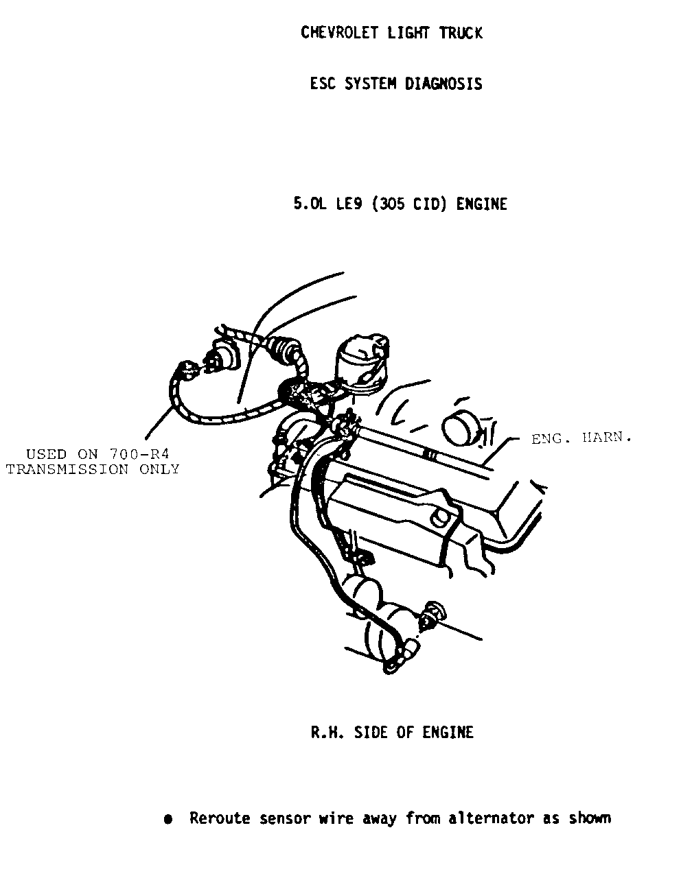
6. Make sure that the sensor wire is not routed close to the alternator (as on "G" vans) or any of the spark plug wires - re-route it per the attached sketch if necessary.
7. Eliminate any obvious mechanical noise internal to the engine that could be the cause of false retard. Examples of possible problem noises are:
Fuel pump. Abnormally loud valve lifter. Loose accessory mounting brackets.
8. Disconnect sensor wire from sensor. Clean inside connector by scraping with a small screwdriver. Compress the connector contact by lightly squeezing the body of the connector with pliers. Clean sensor pin. Inspect sensor for bending or bent pin. If deformed, replace sensor. Reinstall connector to sensor.
9. Check for a failed sensor by doing the following:
Disconnect 10-pin connector from ESC controller.
Measure resistance from pin B to pin K in connector. If resistance is not 175-375 OHMS, disconnect sensor wire from sensor and measure resistance from sensor terminal to ground. If resistance is again not 175-375 OHMS, replace sensor. Reconnect sensor wire to sensor and 10-pin connector to controller. Test drive vehicle.
10. If after performing Steps 1-9, and if the vehicle still does not perform satisfactorily, the following steps may be taken to disable the ESC system. However, they should be performed only as a "last resort".
Disconnect 4-pin connector at distributor and jumper pins A and C in distributor connector together. This should be made to a permanent connection and can be accomplished by cutting the male connector off the harness, together with approximately three (3) inches of wire. Tape up the exposed harness wire ends. Strip the insulation back on the wires from pins A and C of the male connector and solder the wires together. Tape up the exposed wire and insert male connector back into female connector on distributor.
For 1981 vehicles - remove distributor and install a 1982 distributor (P/N 1103465) - or remove distributor, install main shaft assembly (P/N 1979897) and vacuum control (P/N 1973691) and reinstall distributor - set initial timing to 0 DEG (TDC).
For 1982 vehicles - set initial timing to 0 DEG (TDC).
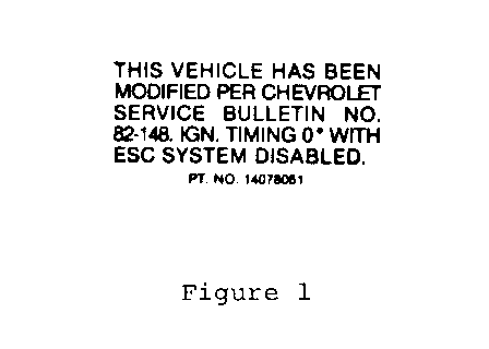
11. Clean an area near the tune up label with a degreasing type cleaning fluid (not soap and water) and install the Service Modification Label, P/N 14078051.
One (1) strip (10 labels) of labels will be sent to each dealer along with four (4) bulletins. If additional labels are required, order them through:
General Motors Photographic 899 West Baltimore Detroit, MI 48202 ATTN: Department 56
Labor Operation Number: T1100
Labor Time: "C-K" .7 hours "G" .9 hours


General Motors bulletins are intended for use by professional technicians, not a "do-it-yourselfer". They are written to inform those technicians of conditions that may occur on some vehicles, or to provide information that could assist in the proper service of a vehicle. Properly trained technicians have the equipment, tools, safety instructions and know-how to do a job properly and safely. If a condition is described, do not assume that the bulletin applies to your vehicle, or that your vehicle will have that condition. See a General Motors dealer servicing your brand of General Motors vehicle for information on whether your vehicle may benefit from the information.
