CAMPAIGN: LH LOWER CONTROL ARM CRACKING

SUBJECT: LH LOWER CONTROL ARM CRACKING
-- RE-ISSUE --
Models: 1985-86 P3, G3 & C3
TO: ALL GENERAL MOTORS DEALERS
THIS BULLETIN CANCELS AND SUPERSEDES CAMPAIGN BULLETIN 2D04 ISSUED FEBRUARY 1992. ALL COPIES OF THE ORIGINAL BULLETIN SHOULD BE DESTROYED.
THE SERVICE PROCEDURE AND THE PARTS INFORMATION AND LABOUR CLAIM INFORMATION SECTIONS HAVE BEEN REVISED.
General Motors of Canada Limited has determined that a defect which relates to motor vehicle safety exists in certain 1985-86 P3 commercial model trucks with 350 gas, or 6.2L diesel engines, 1985-86 G3 model vans with 350 gas or 6.2L diesel engines and 1985-86 C3 model trucks built without heavy duty front suspensions. The left-hand lower control arm can crack starting at the rear flange and progress to the ball joint mounting hole and eventually cause the lower ball joint to separate from the control arm. If this happens, a loss of vehicle. steering control can occur which could result in a vehicle crash without prior warning.
To prevent this condition from occurring, dealers are to install a reinforcement brace to the left-hand lower control arm.
VEHICLES INVOLVED:
Involved are CERTAIN 1985-86 P3 commercial model trucks with 350 gas engines (LT9) or 6.2L diesel engines (LL4), 1985-86 G3 model vans with 350 gas engines (LT9) or 6.2L diesel engines (LL4) with or without school bus equipment (B3D) and without recreational vehicle chassis modification (9A2) or heavy duty front suspension (F42), and 1985-86 C3 model trucks built without heavy duty front suspension (F42) built within the following VIN break points:
Model Year Assembly Model Plant Plant Code From Through ----------------------------------------------------------------------------- 1985 C3 Janesville "J" SOP EOP C3 Oshawa "1" SOP EOP C3 Pontiac "V" SOP EOP C3 St. Louis "S" SOP EOP
G3 Scarborough "4" SOP EOP G3 Lordstown "7" SOP EOP
P3 Detroit "3" SOP EOP
1986 C3 Janesville "J" SOP EOP C3 St. Louis "S" SOP EOP
G3 Scarborough "4" SOP EOP G3 Lordstown "7" SOP EOP
P3 Detroit "3" SOP EOP
All affected vehicles have been identified by the VIN fisting provided to involved dealers with this bulletin. Any dealer not receiving a listing was not shipped any of the affected vehicles.
DEALER CAMPAIGN RESPONSIBILITY:
All unsold new vehicles in dealer's possession and subject to this campaign must be held and inspected/repaired per the Service Procedure of this Campaign Bulletin before owners take possession of these vehicles.
Dealers are to perform this campaign on all involved vehicles at no charge to owners, regardless of kilometres traveled, age of vehicle, or ownership, from this time forward.
Whenever a vehicle subject to this campaign is taken into your new or used vehicle inventory, or it is in your dealership for service, you are to ensure the campaign correction has been made before selling or releasing the vehicle.
Owners of vehicles recently sold from your new vehicle inventory are to be contacted by the dealer, and arrangements made to make the required correction according to instructions contained in this bulletin.
In summary, whenever a vehicle subject to this campaign is taken into your new or used vehicle inventory, or is in your dealership for service in the future, please take the steps necessary to be sure the campaign correction has been made before selling or releasing the vehicle.
CAMPAIGN PROCEDURE:
Refer to Section 4 of the Service Policies and Procedures Manual for the detailed procedure on handling Product Campaigns. Dealers are requested to complete the campaign on all transfers as soon as possible.
OWNER NOTIFICATION:
All owners of record at the time of campaign release are shown on the attached computer listing and have been notified by first class mail from General Motors. The listings provided are for campaign activity only and should not be used for any other purpose.
PARTS INFORMATION:
Parts required to complete this campaign should be ordered through regular channels, as follows:
Part Number Description Quantity/Vehicle ----------- ----------- ---------------- 15624685 Lower Control Arm Reinforcement Kit 1
9766424 Ball Joint If Required
NOTE: Disregard instructions enclosed in kit #15624685. Use the procedures from the Service Procedure portion of this bulletin instead.
PARTS AND LABOUR CLAIM INFORMATION:
Credit for the campaign work performed will be paid upon receipt of a properly completed campaign claim card or DCS transmission in accordance with the following:
Repair Code Description Time Allowance ----------- ----------- -------------- 1A Inspect Lower Control Arm - No Action Required 3
2A Inspect - Install Reinforcement Kit and Measure 8 Ball Joint
3A Inspect - Replace Aftermarket Ball Joint 1.3
Time allowance includes 0. 1 hour for dealer administrative detail associated with this campaign. Parts credit will be based on dealer net plus 30% to cover parts handling.
SERVICE PROCEDURE:
INSTRUCTION FOR INSTALLATION OF REINFORCEMENT KIT
NOTE: Disregard instructions enclosed in kit #15624685. Use the procedures listed in this Service Procedure instead.
PRELIMINARY INSPECTION OF THE CONTROL ARM
1. Raise left front of vehicle and support it with suitable safety stands.
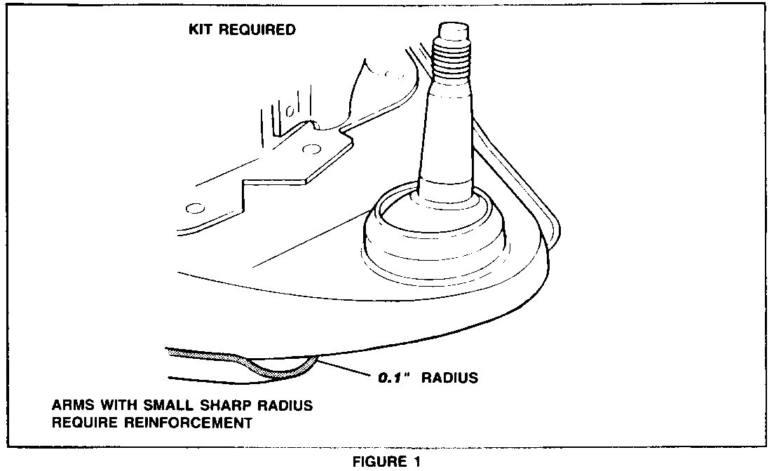
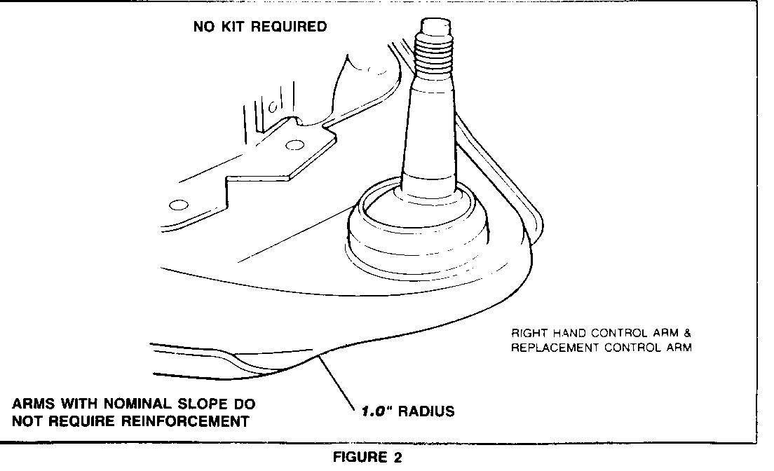
2. Inspect left-hand lower control arm to determine if subject vehicle requires modification. Arms subject to kit installation will have a small radius of 2.54mm (0.1 inch) at flange-to- nose transition (Figure 1) instead of intended 25.4mm (1.0 inch) nominal radius (Figure 2). All right-hand lower control arms have proper radius and may be used for comparison.
NOTICE: Some 1985 and 1986 vehicles may have had their lower control arms replaced. If inspection of left-hand lower control arm indicates 25.4mm (1.0 inch) nominal radius as shown in Figure 2, control arm does NOT require reinforcement kit. If this is the case, install Campaign Identification Label and submit a product campaign claim for "Inspect Control Arm - No Action Required."
INITIAL POSITIONING OF THE REINFORCEMENT
1. Clean left-hand lower control arm of all dirt, rust, grease and undercoating from spring pocket outboard. Clean both top and bottom areas of control arm. This will ensure good mechanical contact of reinforcement and U-bolt to control arm and ball joint flange. Use appropriate solvents and/or a wire brush as required.
NOTICE: If control arm and reinforcement are not thoroughly cleaned, U-bolt may "walk" off bottom of ball joint when it is tightened.
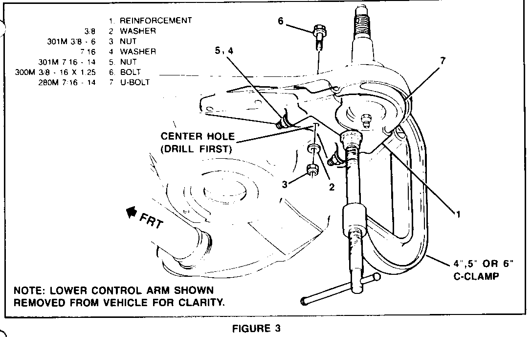
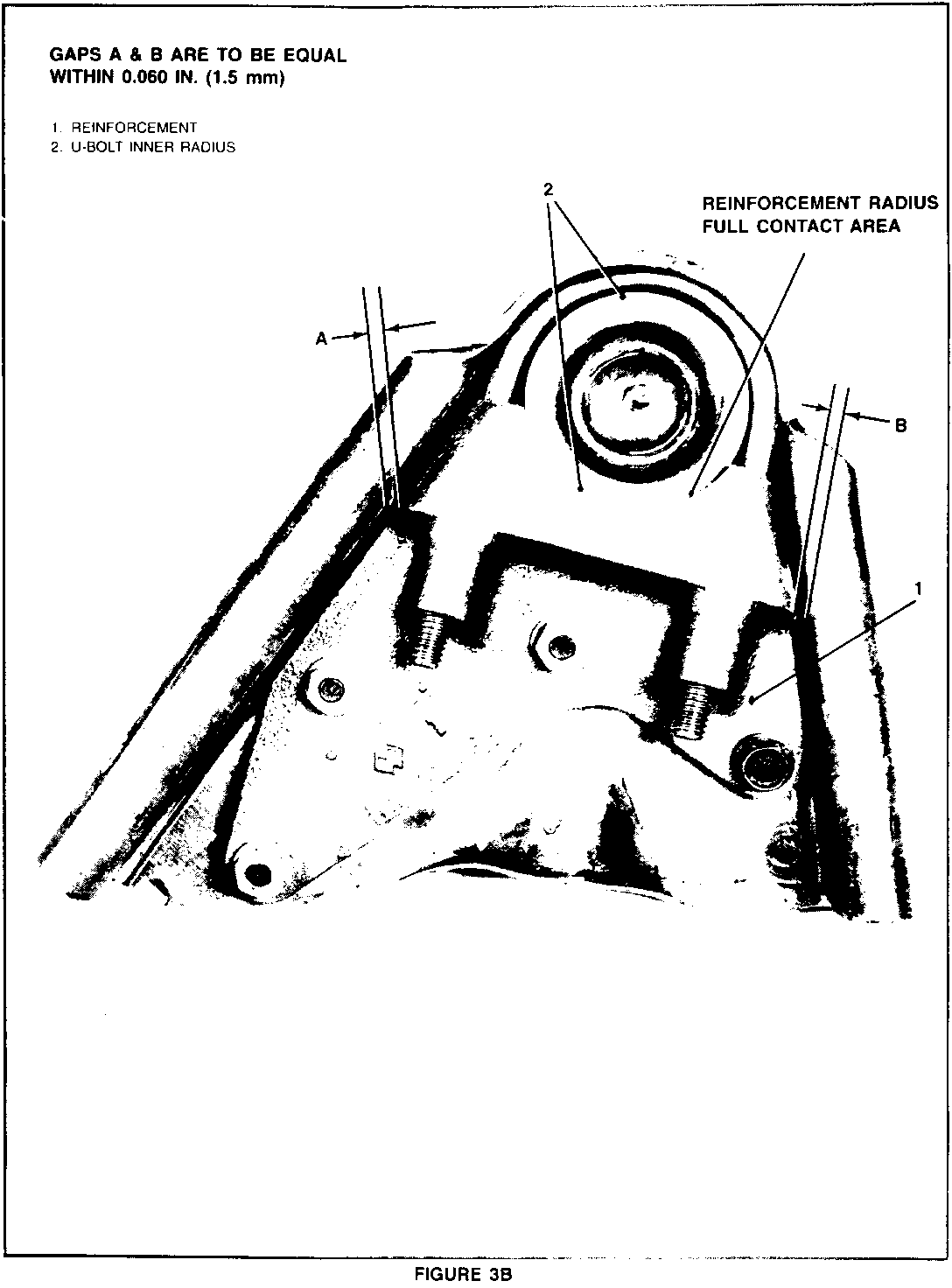
2. Centre reinforcement (Figure 3B, "1") between flanges. Gaps A & B shown in Figure 3B are to be equal within 1.5mm (0.060 inch). Secure reinforcement with a 4 in., 5 in. or 6 in. "C" clamp.
NOTICE: Reinforcement is designed to fit ball joints with a bottom diameter of 66mm (2.60 inches) or greater, and is installed CORRECTLY when ball joint makes full contact with reinforcement radius (Figure 3B), not just centre section of reinforcement.
Technicians may find that ball joint does not make full contact with radius of reinforcement when reinforcement is centred between flanges. In this event, it is possible that an aftermarket ball joint with a bottom diameter of less than 66mm (2.60 inches) has been installed. This does not allow for full contact with radius of reinforcement, and when this happens, only a small section of ball joint will be centred on reinforcement.
If this occurs, make certain ball joint is clean as described in Step 1 and then measure bottom diameter of ball joint with calipers. If measurement is LESS THAN 66mm (2.60 inches), ball joint must be replaced with a Genuine GM ball joint.
3. Install U-bolt (Figure 3, "7") and torque to approximately 10 N.m (7 lb. ft.).
NOTICE: THIS STEP MUST BE PERFORMED BEFORE PROCEEDING TO STEP 4.
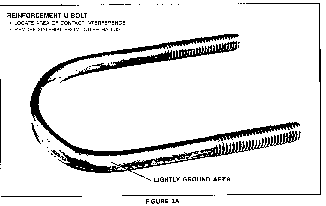
When correctly installed, U-bolt will be about even with bottom of ball joint. U-bolt is NOT designed to fit into galley of control arm. On some vehicles U-bolt may contact flange edge of control arm and interfere with correct installation. In these cases you may remove only enough material (LIGHTLY grind) (Figure 3A) from outer radius of U-bolt to allow clearance between U-bolt and control arm (Figures 3, "7").
4. Drill centre hole with 9.5nim (3/8") drill. Reinforcement (Figure 3, "1") has been designed to be used as a drill guide. Keep drill as perpendicular as possible when drilling.
5. Install one 3/8-16 bolt (Figure 3, "6"), nut (Figure 3, "3"), and washer (Figure 3, "2") in centre hole and torque to approximately 18 N.m (13 lb. ft.).
6. Remove "C" clamp.
7. Drill three remaining holes in any sequence.
8. Disassemble reinforcement (Figure 3, "1") and U-bolt (Figure 3, "7") from control, arm and remove all chips or burrs from reinforcement.
INSTALLATION OF REINFORCEMENT
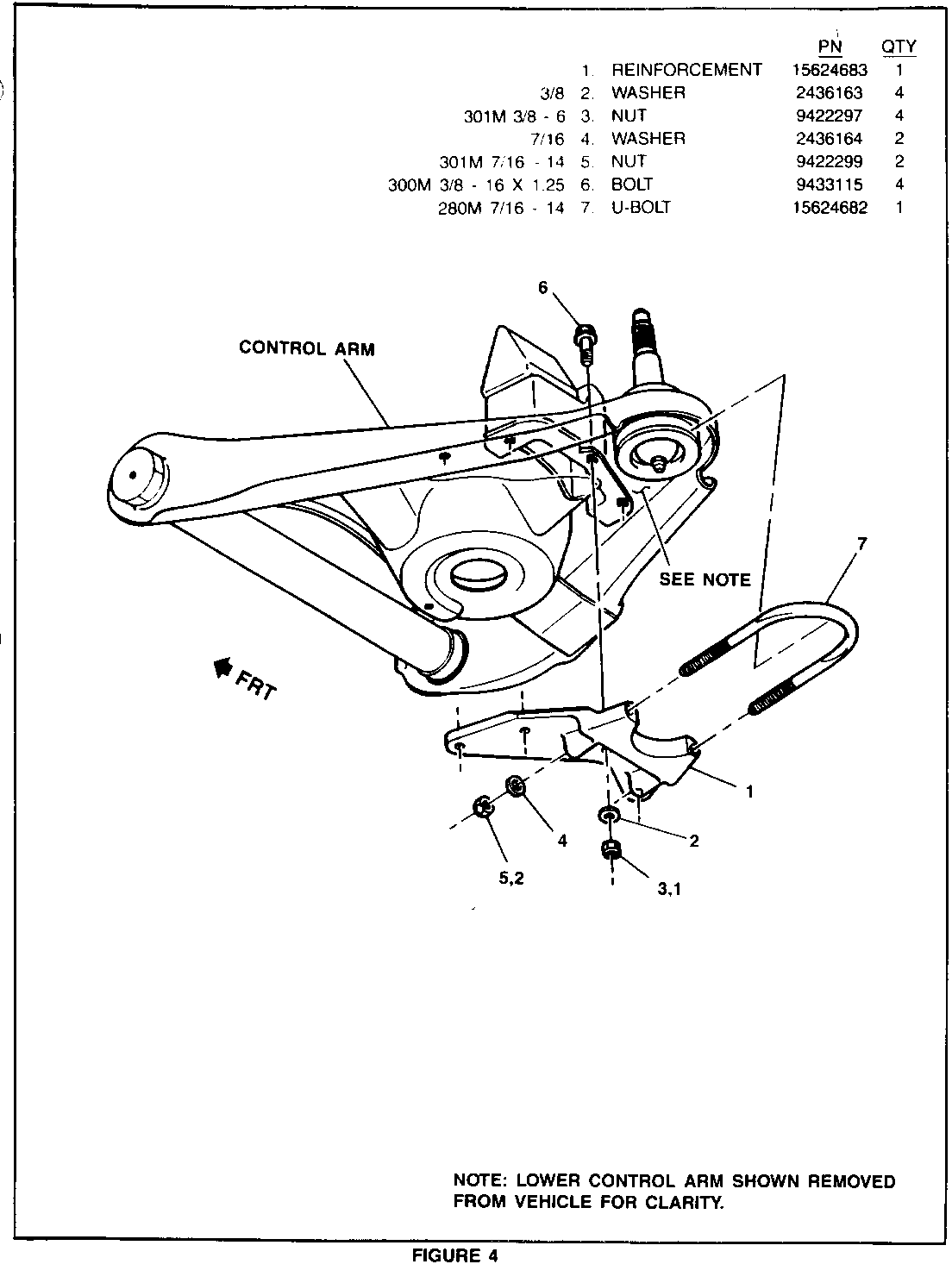
1. Reinstall reinforcement (Figure 4, "I") and U-bolt (Figure 4, "7"). Hand start all bolts. Tighten U-bolt nuts (Figure 4, "5") to approximately 22 N.m (16 lb. ft.). Make sure U-bolt is ALIGNED with bottom edge of ball joint and is NOT COCKED while continuing to torque.
NOTE: If rearmost bolt head flange interferes with bump stop bracket, install bolt from bottom of control arm.
2. Torque 3/8-16 bolts (Figure 4, "6") to 37-43 N.m (27-32 lb. ft.). Tighten centre bolt first and remainder in any sequence.
3. Torque U-bolt nuts (Figure 4, "5") to 40-46 N.m (30-34 lb. ft.).
4. Lower vehicle.
5. Install "Campaign Identification Label."
INSTALLATION OF CAMPAIGN IDENTIFICATION LABEL
Clean surface of radiator upper mounting panel and apply a Campaign Identification Label. Make sure the correct campaign number is inserted on the label. This will indicate that the campaign has been completed.
Dear General Motors Customer:
General Motors of Canada Limited has determined that a defect which relates to motor vehicle safety exists in certain 1985-86 P3 commercial model trucks with 350 gas or 6.2L diesel engines, 1985-86 G3 model vans with 350 gas or 6.2L diesel engines and 1985-86 C3 model trucks built without heavy duty front suspensions. The left-hand lower control arm can crack starting at the rear flange and progress to the ball joint mounting hole and eventually cause the lower ball joint to separate from the control arm. If this happens, a loss of vehicle steering control arm can occur which could result in a vehicle crash without prior warning. To prevent this condition from occurring, your dealer will install a reinforcement brace to the left-hand lower control arm.
Please contact your GM dealer as soon as possible to arrange a service date.
If parts are required, ask your dealer for details regarding their availability. If parts are not in stock, they can be ordered before scheduling your service date.
This letter identifies your vehicle. Presentation of this letter to your dealer will assist their Service personnel in completing the necessary correction to your vehicle in the shortest possible time. Subsequent to contacting your dealer, further assistance, if required, may be obtained from our Customer Assistance Centre, toll free, by calling 1-800-263-3777 (English), or 1-800-263-7854 (French).
We are sorry to cause you this inconvenience; however, we have taken this action in the interest of your continued satisfaction with our products.
General Motors bulletins are intended for use by professional technicians, not a "do-it-yourselfer". They are written to inform those technicians of conditions that may occur on some vehicles, or to provide information that could assist in the proper service of a vehicle. Properly trained technicians have the equipment, tools, safety instructions and know-how to do a job properly and safely. If a condition is described, do not assume that the bulletin applies to your vehicle, or that your vehicle will have that condition. See a General Motors dealer servicing your brand of General Motors vehicle for information on whether your vehicle may benefit from the information.
