RWAL BRAKE SENSITIVITY REPLACE WITH '90 BRAKE ASSY.

SUBJECT: RWAL BRAKE SENSITIVITY (REPLACE WITH 1990 BRAKE ASSEMBLIES
VEHICLES AFFECTED: 1988-89 C3, K3, W/RPO R05 (DUAL REAR WHEELS)
Some owners of 1988-89 C3 and K3 models equipped with dual rear wheels, may comment about a momentary rear tire 'chirp' during brake application with the vehicle unloaded. A service procedure has been developed for this condition, consisting of replacing the rear wheel backing plate assemblies. The assemblies consist of the backing plates with all brake components mounted on them. With the replacement of the backing plates, the hub and drum assembly must also be replaced.
A. Brake Backing Plate, Hub and Drum Assembly, and Axle Shaft Removal
1. Raise vehicle and support with suitable safety stands.
2. Remove wheel and tire assembly.
If wheel and tire assembly does not break free of the hub using standard procedures:
A. Tighten all the lug nuts on the affected wheel. Do not torque.
B. Loosen each nut two turns.
C. Lower vehicle to floor.
D. Rock the vehicle from side to side to loosen the wheel or rock the vehicle from forward to reverse, allowing the the vehicle to move several feet in each direction. Apply quick, hard jabs on the pedal to loosen the wheel.
E. Raise the vehicle and remove the lug nuts and the wheel.
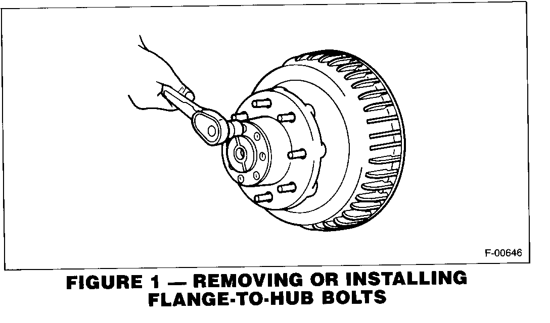
3. Remove axle shaft (see Figure 1).
A. Remove bolts (55) holding axle shaft to hub.
B. Rap axle shaft (53) with a soft-faced hammer to loosen the shaft.
C. Grip the rib on the shaft (53) with a locking plier and twist to start shaft removal.
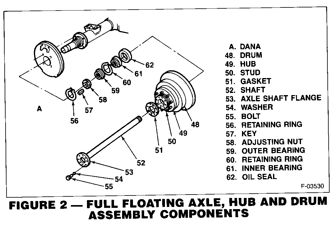
4. Remove hub and drum assembly (Figure 2).
A. Remove retaining ring (56).
B. Remove key (57).
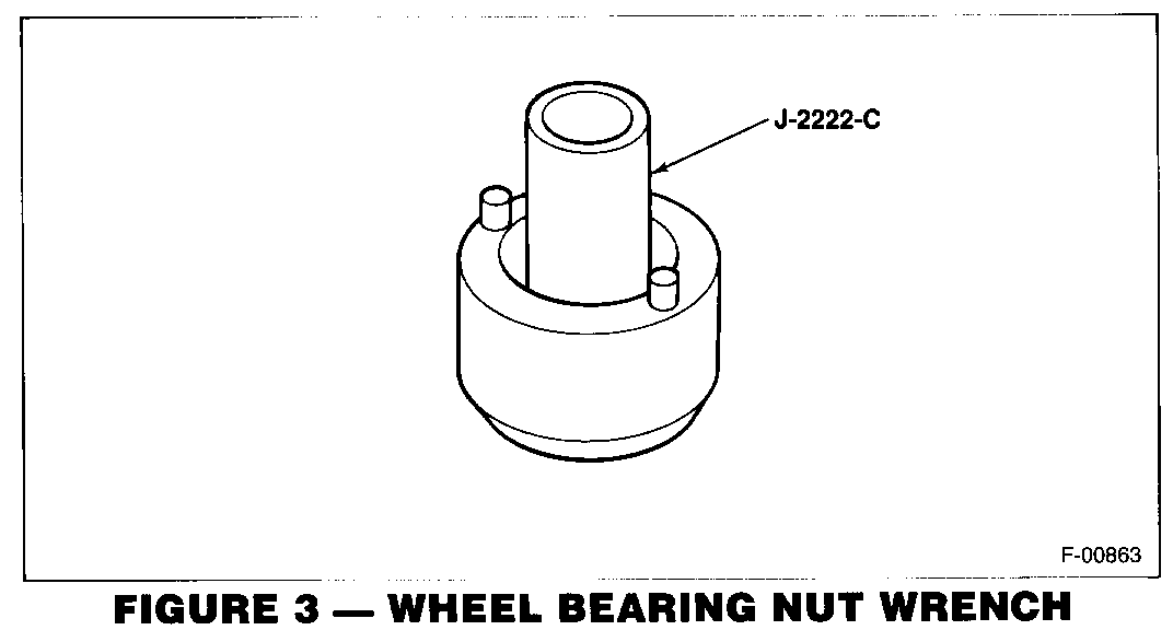
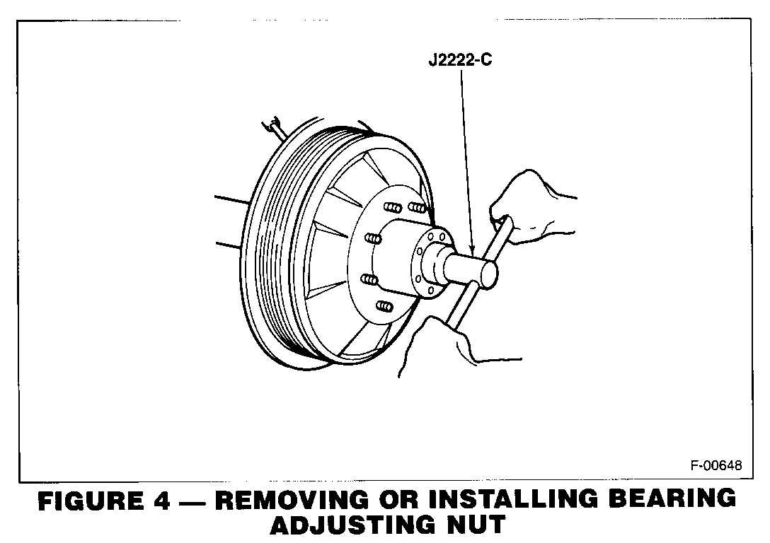
C. Remove bearing adjusting nut (58). Use tool J-2222-C as shown in figures 3 & 4.
D. Remove and discard hub and drum assembly.
NOTE: If difficulty is encountered in removing the drum:
(1) Make sure the parking brake is released.
(2) Back off the parking brake cable adjustment.
(3) Back off the star wheel on the brake adjuster screw.
5. Remove brake backing plate (Figure 2).
NOTE: Backing plate, brake shoes, and brake components cables are removed and replaced as an assembly.
A. Remove brake line from wheel cylinder inlet.
B. Loosen adjusting nut on parking brake cable. Remove parking brake cable from lever on backing plate. Bend in retaining fingers and remove cable.
C. Remove 4 bolts and washers holding backing plate to axle.
D. Remove and discard backing plate. If plate does not come off readily, use a soft-faced hammer to loosen plate from axle housing.
B. Re-installation of Backing Plate, Hub and Drum Assembly, and Axle Shaft
1. Re-install brake backing plate.
A. Install backing plate on axle housing.
B. Install four bolts and washers, and torque to 160 Nm (120 lb-ft).
C. Connect brake line to cylinder inlet.
D. Install parking brake cables into backing plates.
NOTE: Left hand cable routes under leaf spring.
E. Connect cable to parking brake lever on backing plate.
F. Make sure all retaining fingers are through the hole.
2. Re-install hub and drum assembly (Figures 2 & 4).
A. Install new hub and drum assembly (48, 49) on axle tube. Be sure the bearings and the oil seal are positioned properly.
B. Apply a light coat of high melting point EP bearing lubricant to the contact surfaces and the outside of the axle tube.
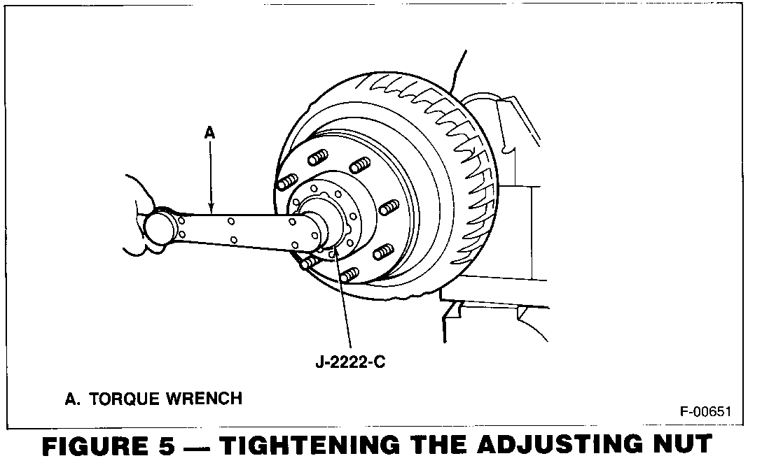
C. Install the adjusting nut (58). Using tool J-2222-C, torque nut to 68 Nm (50 lb-ft) while turning the hub. See Figure 5.
D. Install key (57) and retaining ring (56).
3. Re-install axle shaft (52) (Figures 2 & 4).
A. Remove old gasket or RTV from axle shaft flange (53). Also clean outside face of hub assembly (49).
B. Install axle shaft (52). Be sure shaft splines mesh with differential side gear. Align axle shaft holes with hub holes.
C. Install bolts (55) in shaft holes and torque to 156 Nm (1 15 lb-ft).
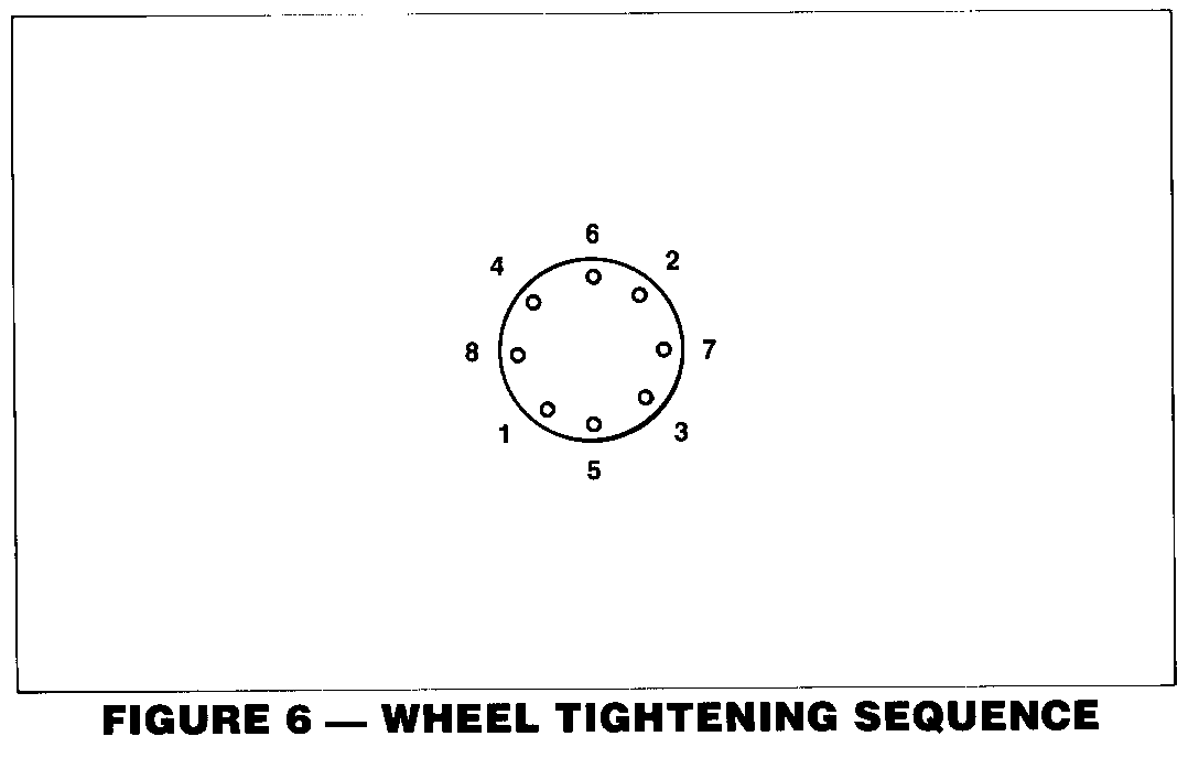
D. Install wheel and tire assembly on hub and torque to 70 Nm (125 lb-ft). See Figure 6 for torque sequence.
C. Service Brake Adjustment
Service brakes must be adjusted after installation of new drums and brake shoes.
1. Bleed rear brake lines and cylinders as follows:
A. If it is known that no air has been introduced into the master cylinder, it is only necessary to bleed the two rear wheel cylinders and lines.
B. Fill master cylinder reservoir with brake fluid. Use Delco Supreme 11 brake fluid 12345347 or Dot-3. Maintain fluid level in reservoir during the bleeding operation.
C. Attach a hose to the wheel cylinder bleeder screw. Immerse opposite end of hose in a container partially filled with clean brake fluid. Bleed right rear wheel first.
D. Slowly depress the brake pedal one time and hold.
E. Loosen the bleeder screw to purge the air from the wheel cylinder.
F. Tighten the bleeder screw and slowly release the pedal.
G. Wait 15 seconds, then repeat this sequence including the 15 second wait until all air has been purged from the wheel cylinder.
H. Repeat procedure with left rear wheel.
I. Check the brake pedal for sponginess and the brake warning lamp for an indication of an unbalanced pressure. Repeat entire bleeding procedure to correct either of these conditions.
2. Adjust service brakes:
A. Remove adjuster hole cover.
B. Adjust brake adjusti.ng screw until wheel can just be turned by hand.
C. The brake drag should be equal at both wheels.
D. Back off adjusting screw 33 notches.
IMPORTANT: Brakes should have no drag after the screw has been backed off about 15 notches. If a heavy drag is present, refer to parking brake adjustment in following paragraph.
E. Reinstall adjuster hole cover.
F. Check parking brake adjustment.
D. Parking Brake Adjustment
The parking brakes must be adjusted whenever the brake shoes or drums have been replaced.
1. Service brakes must be adjusted properly before proceeding to parking brake adjustment.
2. Check the parking brake system for free operation. The brake lever must return to the released position without sticking or binding. If a problem is present, check the cable routing for kinks or binding. Clean and lubricate the parking brake assembly and cables with Delco brake lube or equivalent.
3. Loosen the equalizer nut.
4. Set the parking brake pedal to four clicks.
5. Adjust equalizer nut until the wheels rotate forward with a moderate drag.
6. Release the parking brake and rotate the rear wheels. There should be no drag.
E. Check-Out of Replacement
1. Check axle and brake operation.
2. Check for fluid leaks and road test vehicle.
F. Service Parts
SERVICE PARTS INFORMATION
Part Number Description Quantity
15622341 Plate and brake assembly 1 rear flange, LH
15622340 Plate and brake assembly 1 rear flange, RH
15649164 Hub and drum assembly 2
General Motors bulletins are intended for use by professional technicians, not a "do-it-yourselfer". They are written to inform those technicians of conditions that may occur on some vehicles, or to provide information that could assist in the proper service of a vehicle. Properly trained technicians have the equipment, tools, safety instructions and know-how to do a job properly and safely. If a condition is described, do not assume that the bulletin applies to your vehicle, or that your vehicle will have that condition. See a General Motors dealer servicing your brand of General Motors vehicle for information on whether your vehicle may benefit from the information.
