SERVICE MAN. UPDATE - SEC. 6C2 DIESEL FUEL INJ. REV. ADJ. PRO

Subject: FUEL INJECTION ADJUSTMENT PROCEDURE REVISED
Model and Year: 1991-93 C/K, R/V, G, AND P TRUCKS
The following represents new and/or revised information for Section 6C2 in the 1991-93 C/K, RN, G, and P service manuals.
THROTTLE POSITION SENSOR DIAGNOSIS:
To identify Diagnostic Trouble Codes 21, 22, and 23 for the throttle position sensor, refer to "Throttle Position Sensor Diagnostic Trouble Codes." For diagnosis of the listed Diagnostic Trouble Codes, refer to SECTION 6E2 of the vehicle service manual. If it's diagnosed that the throttle position sensor needs adjustment, follow the adjusting procedure as follows:
59-6 tables 59
Book # Section # T3185 ---------------------- THROTTLE POSITION SENSOR DIAGNOSTIC TROUBLE CODES ------------------------------------------------
DTC AND CIRCUIT PROBABLE CAUSE DEFAULT ACTION --------------- -------------- -------------- 21 DTC 21 will set if o Set line pressure to signal voltage maximum Throttle Position Sensor has been greater than o Fixed shift points. Signal Voltage High 4.9 volts for 1 second. o Inhibit 4th gear. o Inhibit TCC operation.
22 DTC 22 will set if TP o Set line pressure to signal voltage maximum Throttle Position Sensor is less than .20 volt o Fixed shift points. Signal Voltage Low for 1 second. o Inhibit 4th gear. o Inhibit TCC operation.
23** DTC 23 will set if o Fixed shift points. signal voltage is Throttle Position Sensor not between .25 and o Set EGR schedule. 1.35 volts for Not Calibrated 30 seconds with engine between 550 and 650 RPM. NOTES: ----- ** Code only used with ECM and PCM equipped vehicles
THROTTLE POSITION SENSOR (TPS) ADJUSTMENT:
IMPORTANT: *There are two throttle position sensors used for the models indicated in this SMU. Refer to the "Throttle Position Sensor Data" chart to make sure the proper throttle position sensor settings are followed.
Tools Required: J 33043-2 TP Sensor Gage Block Set
J 39200 Digital Multimeter (or equivalent).
ADJUST:
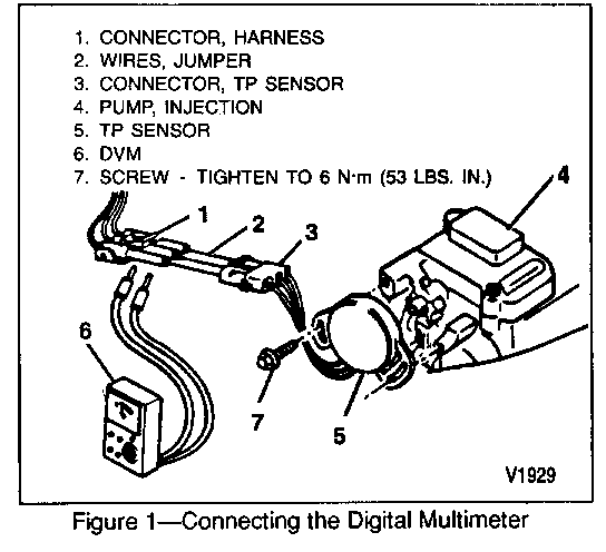
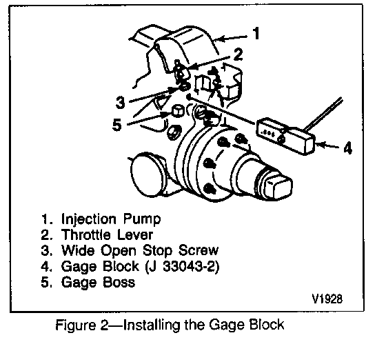
------ (Figures 1 and 2)
1. Remove the air cleaner and related hoses. Refer to SECTION 6C.
2. Disconnect the TP sensor connector and insert jumper wires between the sensor and harness. Jumpers can be made using the following terminal P/N information. Refer to the "Throttle Position Sensor Data" cha rt. Three ju mper wires or their equivalent will be necessary (figure 1).
3. Turn key to "ON" (engine not running).
4. Using a digital multimeter J 39200 or equivalent, measure the voltage from the TP sensor connector terminals "A" to "C." This is the voltage reference.
IMPORTANT: *The TP sensor voltage is displayed by the TECH 1, however, it's recommended that only the multimeter be used to set the TP sensor as the TECH 1 voltage may read higher than the multimeter.
5. Multiply the voltage ratio x voltage reference number (from step 4) = required TP sensor voltage setting.
Example: 0.33 (voltage ratio x 4.97 (voltage reference) = 1.64 volts (desired voltage setting).
Refer to the "Throttle Position Sensor Data" chart for calculating the correct TP sensor voltage setting.
6. Insert the 0.646 side of the TP sensor gage block (J 33043-2) between the gage boss on the injector pump and the wide-open stop screw on the throttle lever (figure 2).
7. Rotate the throttle level toward the wide- open position so that the gage block is held firmly in place.
8. Measure the voltage between terminals "B" and "C." This is the TP sensor voltage. It must be within the following specified tolerance of the desired TP sensor voltage setting. Refer to the "Throttle Position Sensor Data" chart.
Example: The actual TP sensor voltage for TP sensor(GM P/N 10137417) should bebetween 1.62 volts and 1.66 volts. For engines equipped with (GM P/N 14071076) TP sensor voltage is between 3.10 and 3.16 volts.
9. If the TP sensor voltage is within tolerance, then proceed to step 12.
10. To adjust the TP sensor, loosen the two attaching screws and rotate the TP sensor to its full left position (facing sensor). Rotate the sensor back to the right until the desired sensor voltage setting (from step 5) isobtained. (Note: To obtain the correct position, the sensor must be rotated to the right from its full left position.)
11. When the correct voltage is obtained, hold the sensor in this position and tighten the attaching screws to 6 N.m (53 lbs. in.).
12. Release the throttle lever and allow it to return to the idle position. Open the throttle lever back against the gage block and re-check the TP sensor. It must be within the specified tolerance of the required TP sensor voltage. Refer to the "Throttle Position Sensor Data" chart. Return to step 10 if adjustment is necessary.
13. Once the TP sensor has been set, the wide-open throttle (WOT) voltage setting must be checked. Multiply the WOT voltage ratio x voltage reference from step 4) = required WOT voltage.
Example: 0.90 (WOT voltage ratio) x 4.97 (voltage reference) = 4.47 (WOT voltage). Refer to the "Throttle Position Sensor Data" chart forthe correct TP sensor part number.
14. To measure the actual WOT voltage, remove the gage block tool. Move the throttle to the wide open position and check the voltage. It must be within the following WOT voltage setting tolerance for the TP sensor specified. Refer to the "Throttle Position Sensor Data" chart.
Example: For engines equipped with TP sensor (GM P/N 10137417) acceptable WOT voltage is between 4.22 to 4.72 volts. For engines equipped with TP sensor (GM P/N 14071076) acceptable WOT is between 4.77 to 4.97 volts.
15. If adjustment is not possible, or if sensor voltage at WOT position is not within the acceptable range, replace the TP sensor and repeat the adjustment procedure again.
16. Turn the engine control switch to "OFF."
17. Remove the jumper wires and reconnect the TP sensor to the vehicle wiring harness.
18. Reinstall air cleaner and related hoses. Refer to SECTION 6C.
Tables 59 59-7
Book # Section # T3186 ---------------------- THROTTLE POSITION SENSOR DATA ----------------------------- YEAR/MODELS ENGINES ----------- ------- 1991-1993 6.5L (RPO L65 VIN F) C/K, G, R/V, and P 6.2L (RPO LL4 VIN J) 6.2L (RPO LH6 VIN C)
APPLICATIONS
ENGINE/TRANSMISSION RPO COMBINATIONS WITH TP SENSOR P/N ------------------------------------------------------- LH6/MD8 P/N 14071076 LH6/MT8/MG5 P/N 14071076 LL4 or L65/MT1/M30 P/N 10137417 Lh6/M30 P/N 10137417
SENSOR SETTING INFORMATION
TP SENSOR P/N 10137417 14071076 VOLTAGE RATION 0.33 **0.63 GAGE BLOCK 0.646 IN. 0.646 in. *WOT VOLTAGE RATIO 0.90 0.98 TERMINAL P/N 12052843 and 12014836 and 12052844 12014837 TP SENSOR SETTING TOLERANCE Plus or Minus Plus or Minus 0.02 Volts 0.03 Volts WOT THROTTLE SETTING TOLERANCE Plus or Minus Plus or Minus 0.25 Volts 0.10 Volts NOTES:
* Wide-open throttle voltage ratio
**Also found on vehicle emissions control information label


General Motors bulletins are intended for use by professional technicians, not a "do-it-yourselfer". They are written to inform those technicians of conditions that may occur on some vehicles, or to provide information that could assist in the proper service of a vehicle. Properly trained technicians have the equipment, tools, safety instructions and know-how to do a job properly and safely. If a condition is described, do not assume that the bulletin applies to your vehicle, or that your vehicle will have that condition. See a General Motors dealer servicing your brand of General Motors vehicle for information on whether your vehicle may benefit from the information.
