SMU - SECTION 10A5 ADDTL. END GATE REPL. PROCEDURE

SUBJECT: END GATE ADDITIONAL REPLACEMENT PROCEDURES
MODEL and YEAR: 1992-1993 C/K SUBURBAN AND UTILITY TRUCKS
The following represents new information for Section 10A5 in the 1993 C/K Models Service Manual.
TRIM PANEL REPLACEMENT:
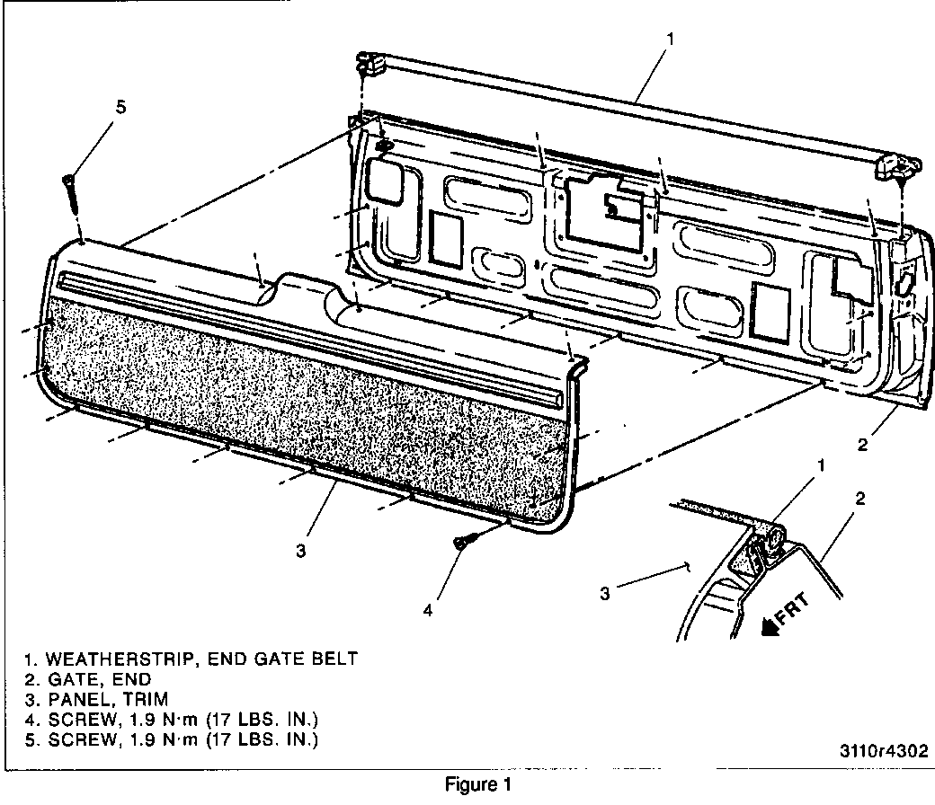
Figure 1-Trim Panel and Belt Weatherstrip
REMOVE OR DISCONNECT (Figure 1)
* Lower the end gate.
1. Trim panel to end gate screws.
2. Trim panel from the end gate.
INSTALL OR CONNECT (Figure 1)
1. Trim panel to the end gate.
NOTICE: Refer to "Notice" on page 10A5-1.
2. Trim panel to end gate screws.
TIGHTEN
* Trim panel to end gate screws to 1.9 N.m (1 7 lbs. in.).
LOCK ASSEMBLY REPLACEMENT:
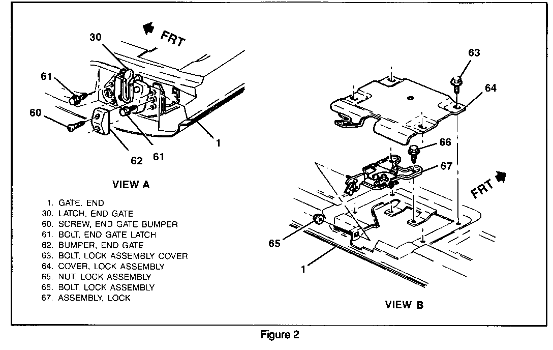
REMOVE OR DISCONNECT (Figure 2)
1. Trim panel. Refer to "Trim Panel Replacement."
2. Lock assembly cover to the end gate bolts.
3. Lock assembly cover.
4. Lock rods from the lock assembly.
* Mark the location of the lock assembly on the end gate.
5. Lock assembly to the end gate bolts.
6. Lock assembly from the end gate.
INSTALL OR CONNECT (Figure 2)
NOTICE: For steps 2 and 5, refer to "Notice" on page 10A5- 1.
1. Lock assembly to the end gate.
* Align the assembly to the marks on the end gate inner panel.
2. Lock assembly to the end gate bolts.
TIGHTEN
* Lock assembly to the end gate bolts to 15 N.m (11 lbs. ft.).
3. Lock rods to the lock assembly.
4. Lock assembly cover.
* Cover must be installed with both gates closed for proper alignment.
5. Lock assembly cover to end gate bolts.
TIGHTEN
* Cover to end gate bolts to 15 N.m (11 lbs. ft.).
6. Trim Panel. Refer to "Trim Panel Replacement."
END GATE BELT WEATHERSTRIP REPLACEMENT:
REMOVE OR DISCONNECT (Figure 1)
1. Trim panel. Refer to "Trim Panel Replacement."
2. Weatherstrip from the end gate flange.
INSTALL OR CONNECT (Figure 1)
1. Weatherstrip onto end gate flange.
a. Install ends of weatherstrip first by pressing fastener into end gate hole.
b. Push center of weatherstrip onto center of end gate flange and work out to ends.
2. Trim panel. Refer to "Trim Panel Replacement."
END GATE WINDOW STRIKER REPLACEMENT:
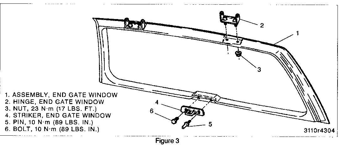
Figure 3-End Gate Window Striker and Hinge
REMOVE OR DISCONNECT (Figure 3)
* Open the end gate window.
1. Striker to the end gate window pin.
2. Striker to the end gate window bolt.
3. Striker from the end gate window.
INSTALL OR CONNECT (Figure 3)
NOTICE: For steps 2 and 3, refer to "Notice" on page 10A5- 1.
1. Striker to the end gate window.
2. Striker to the gate window bolt.
TIGHTEN
* Striker to the end gate window bolt to 10 N.m (89 lbs. in.).
3. Striker to the end gate window pin.
TIGHTEN
* Striker to the end gate window pin to 10 N.m (89 lbs. in.).
END GATE WINDOW HINGE REPLACEMENT:
REMOVE OR DISCONNECT (Figure 3)
1. End gate window supports. Refer to "End Gate Window Support Replacement."
2. Hinge pin retainers and the hinge pins.
3. End gate window assembly from the vehicle.
4. End gate window garnish molding.
5. Hinge to end gate window assembly nuts.
6. Hinge from the end gate window.
INSTALL OR CONNECT (Figure 3)
1. Hinge to the end gate window.
NOTICE: Refer to "Notice" on page 10A5-1.
2. Hinge to end gate window assembly nuts.
TIGHTEN
* Hinge to end gate window assembly nuts to 23 N.m (17 lbs. ft.).
3. End gate window garnish molding.
4. End gate window assembly to the vehicle.
5. Hinge pins and the hinge pin retainers.
6. End gate window supports. Refer to "End Gate Window Support Replacement."
END GATE WINDOW SUPPORT REPLACEMENT:
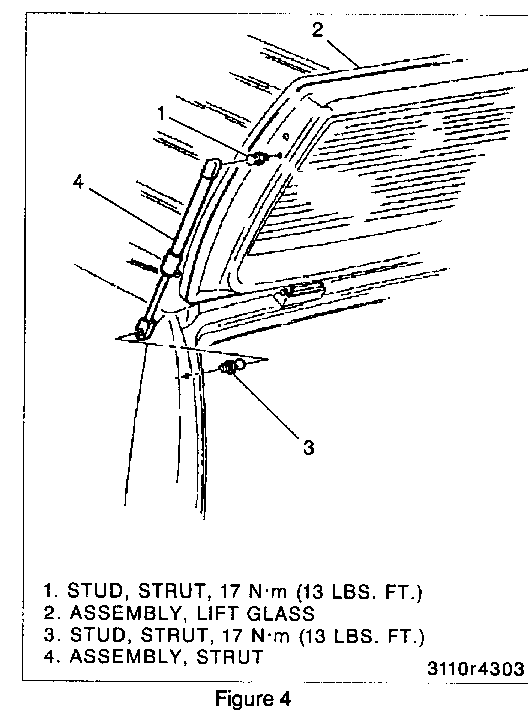
Figure 4-Window Support
CAUTION:
Do not attempt to remove or loosen gas support assembly attachments with glass in any position other than fully open as personal injury may result.
Do not intermix original quality gas supports with other quality supports, since not all supports have the same output level.
REMOVE OR DISCONNECT (Figure 4)
1. Rear window defogger wires attached to the gas supports (if equipped).
2. Ball sockets from the glass side.
* Carefully pry the gas support ball socket from the ball. Insert a small screwdriver between the ball and the ball socket and pull the gas support from the window.
* Support the rear window glass.
3. Ball sockets from the body side.
INSTALL OR CONNECT (Figure 4)
1. Gas support ball socket to the body and glass sides.
* Push the ball socket onto the ball.
2. Rear window defogger wires to the gas supports (if equipped).


General Motors bulletins are intended for use by professional technicians, not a "do-it-yourselfer". They are written to inform those technicians of conditions that may occur on some vehicles, or to provide information that could assist in the proper service of a vehicle. Properly trained technicians have the equipment, tools, safety instructions and know-how to do a job properly and safely. If a condition is described, do not assume that the bulletin applies to your vehicle, or that your vehicle will have that condition. See a General Motors dealer servicing your brand of General Motors vehicle for information on whether your vehicle may benefit from the information.
