Main Shaft Assemble NV4500
- Clean all the parts in a suitable solvent. Air dry all the parts.
- Lubricate the mainshaft bearings with the proper transmission lubricant.
- Check the bearings for rough rotation.
- Inspect the mainshaft gears for the following conditions:
- Inspect related gear surfaces like thrust faces and bearing surface diameters.
- Inspect the synchronizer sleeves for a sliding fit on the synchronizer hubs. The synchronizer hubs must have a force fit on the mainshaft splines.
- Replace a synchronizer hub that does not require a force fit on the mainshaft splines.
- Inspect the synchronizer springs and the keys for damage.
- Inspect the synchronizer rings for excess wear.
- Inspect the synchronizer clutching teeth for the following conditions:
- Inspect the mainshaft drive gear clutching cones for synchronizer ring metal transfer.
- Inspect all the gear teeth for excess wear.
- Remove nicks and burrs with a soft stone or a crocus cloth.
- Replace any components that are bent or show signs of excessive wear. Inspect the mating parts.
- Inspect the bearings and the bearing surfaces for the following conditions:
Important: Do not spin the bearings without a lubricant.
| • | Cracks |
| • | Nicks |
| • | Chipped gear teeth |
| • | High spots (small-shiny spots on the gear teeth mating surface) that could cause gear noise |
| • | Scuffs |
| • | Nicks |
| • | Burrs |
| • | Damage |
| • | Nicks |
| • | Burrs |
| • | Bent cages |
| • | Wear |
| • | Overheating |
| • | Scoring |
| • | Pitted condition |
Assembly Procedure
Tools Required
J 22828 Gear and Bearing Installer
Important: Use TRANSJEL on bearings and contact surfaces.
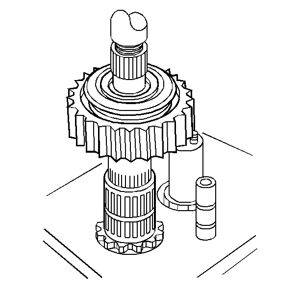
- Install the 1st speed gear bearing and the 1st speed gear.
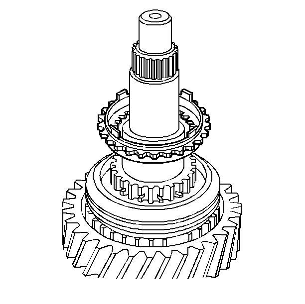
- Install the reverse gear clutch gear and the synchronizer ring. Ensure that the synchronizer ring teeth face down toward the mainshaft shoulder.
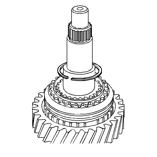
- Install the reverse gear clutch gear retainer ring.
- Install the reverse bearing spacer and the bearing.
- Install the reverse gear and the synchronizer assembly. Rotate the assembly until the gear drops into the fully seated position. If the synchronizer assembly was disassembled, the synchronizer sleeve must be reinstalled with the taper of the sleeve towards the reverse gear.
- Install the reverse gear thrust washer.
- Install the rear mainshaft bearing. Use a hydraulic press and the J 22828 .
- Turn the mainshaft over.
- Install the following parts:
- Install the 1st speed gear synchronizer ring retainer ring.
- Install the 1-2 synchronizer assembly. Install the synchronizer with the taper side of the synchronizer sleeve towards 2nd speed gear.
- Install the 1-2 synchronizer assembly retainer ring. Verify proper orientation of ring by ensuring that the letter R on the hub is up.
- Install the 2nd speed gear synchronizer rings.
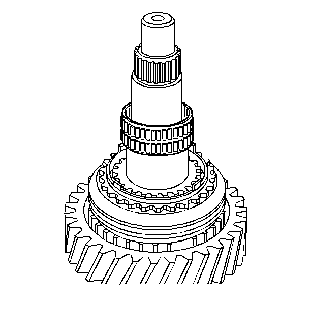
- Install the 2nd speed gear synchronizer ring retainer ring.
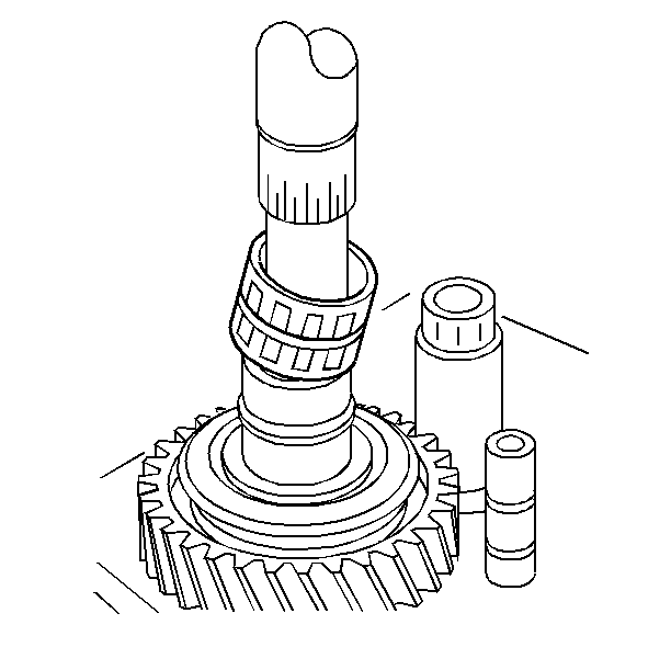
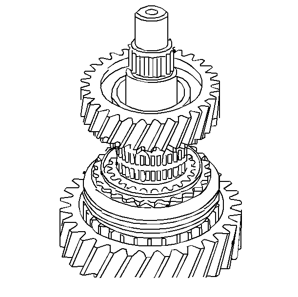
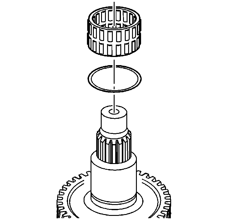
- Install the 2nd speed gear bearing.
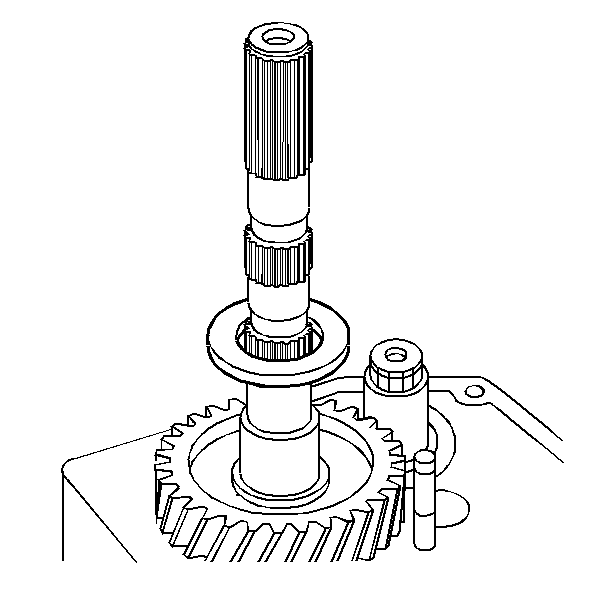
- Install the 2nd speed gear.
- Install the following parts:
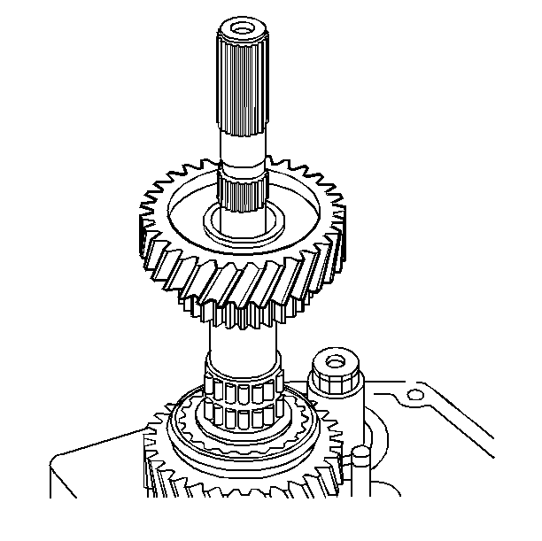
- Install the 3rd speed gear bearing spacer and the bearing.
- Install the 3rd speed gear and the synchronizer assembly. Hold the unit together and press on as an assembly.
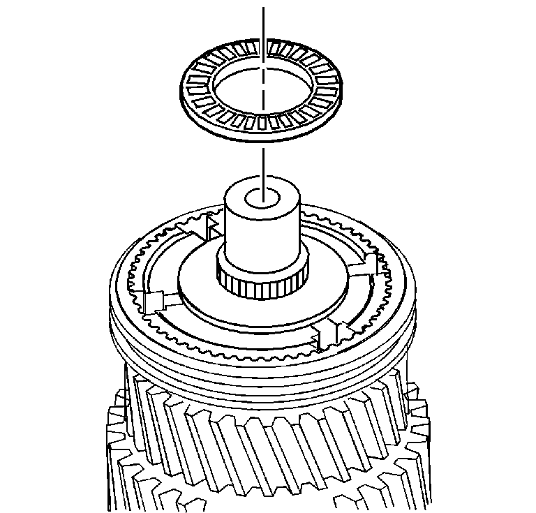
- Install the main drive gear thrust bearing.
- Install the 4th speed gear synchronizer ring.
- Install the 4th speed gear clutch gear.
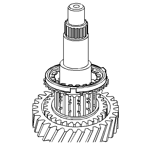
| 9.1. | The 1st speed gear clutch gear |
| 9.2. | The clutch gear snap ring |
| 9.3. | The synchronizer rings |
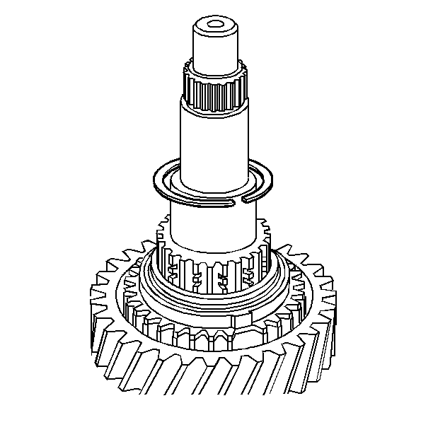
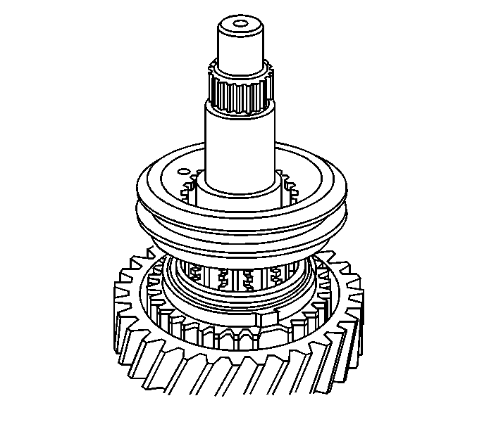
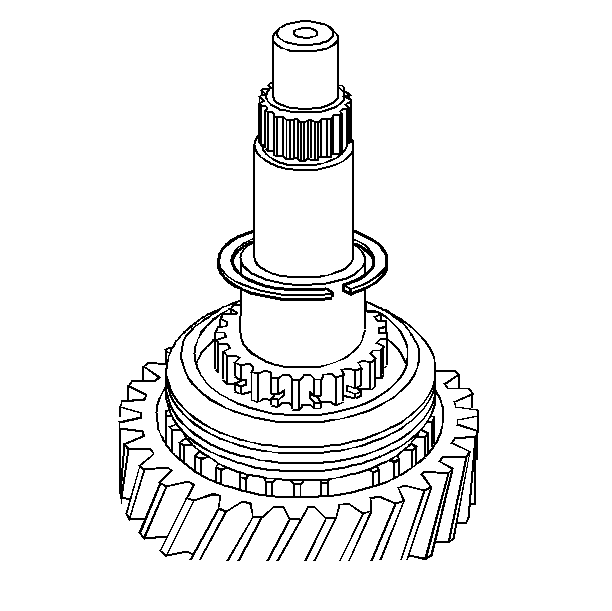
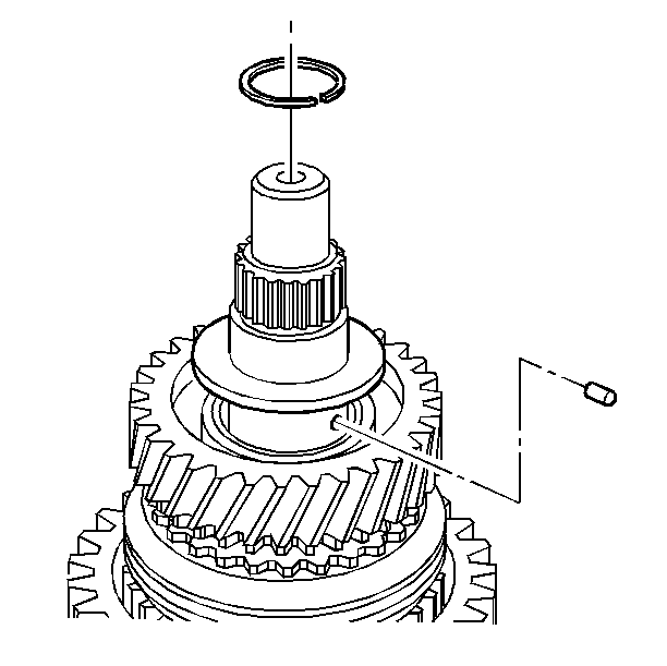
| 17.1. | The 2nd speed gear thrust washer retaining pin |
| 17.2. | The 2nd speed gear thrust washer (Be sure the thrust washer is seated on the gear and the retaining pin.) |
| 17.3. | The 2nd speed gear thrust washer retainer ring. |
Main Shaft Assemble NV3500 4WD
Mainshaft Assembly
Tools Required
| • | Hydraulic Press |
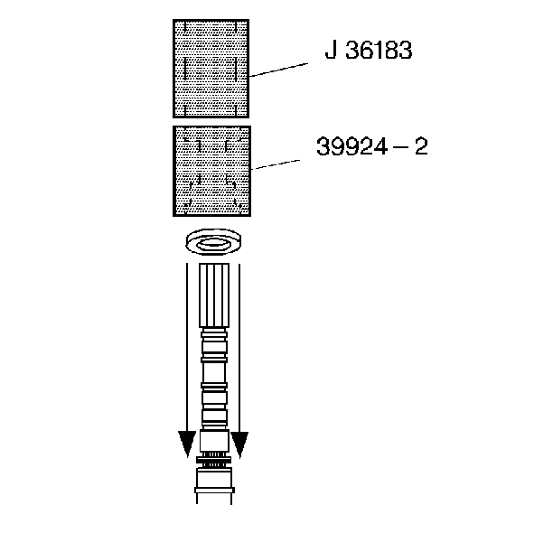
| • | J 36183 Input Shaft Press Tube with Cap |
| • | J 36184 Adapter Press Tube Reducer |
| • | J 39924-1 Reverse Drag Seal Installer |
| • | J 39924-2 5th Speed Gear Drag Seal Installer |
- Install the 5th speed gear drag seal. Use J 39924-2 and J 36183 .
- Install the reverse speed gear drag seal. Use J 39924-1 .
- Install the following components:
- Install the 5th/Reverse speed gear synchronizer.
- Install a new mainshaft snap ring.
- Install the following components:
- Install the 1st speed gear needle bearing assembly
- Install the following components:
- Check the 1st / 2nd speed gear synchronizer assembly scribe marks for correct positions.
- Install the 1st/2nd speed gear synchronizer assembly with both synchronizer rings:
- Install a new mainshaft snap ring.
- Install the following components:
- Install the following components:
- Install the following components:
- Install the following components:
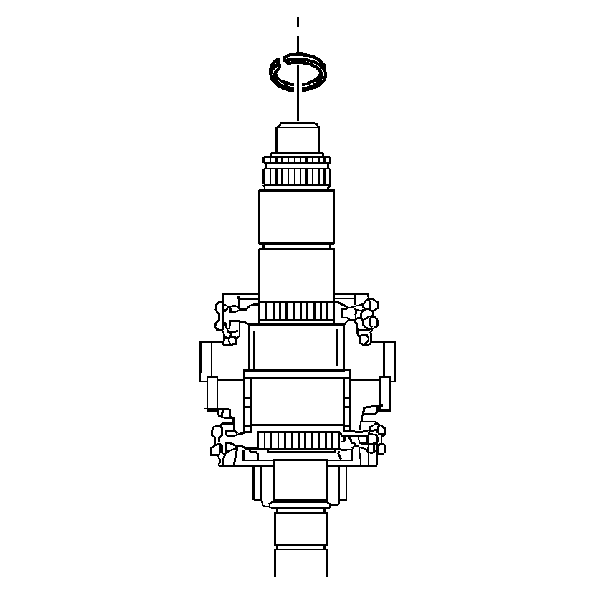
- Check the 3rd/4th speed gear synchronizer assembly scribe marks for correct positions.
- Install the 3rd/4th speed gear synchronizer assembly with both synchronizer rings.
- Install a new mainshaft snap ring.
Important: Some components require an assembly lubricant. Use TRANSJEL or equivalent.
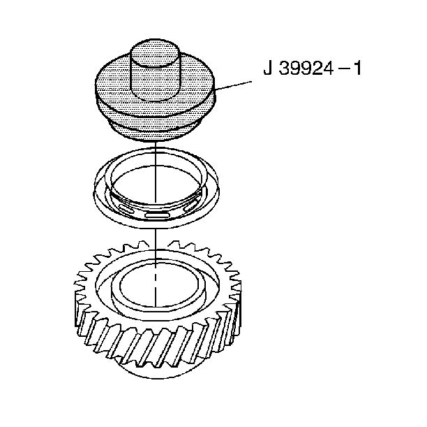
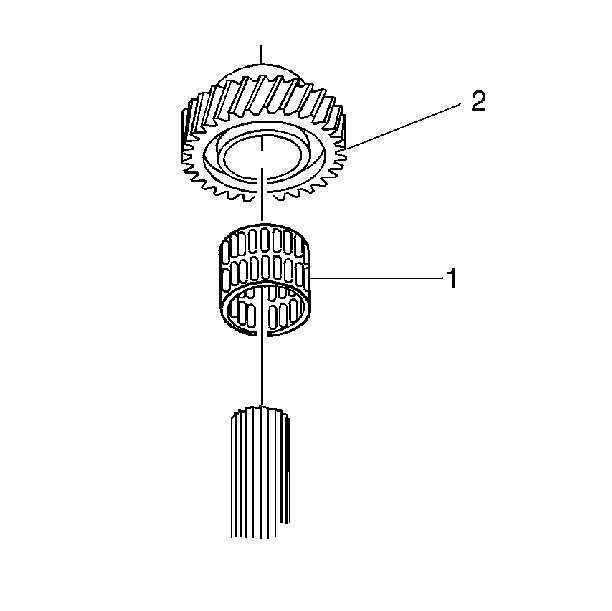
| 3.1. | The reverse speed gear needle bearing assembly. |
| 3.2. | The reverse speed gear. |
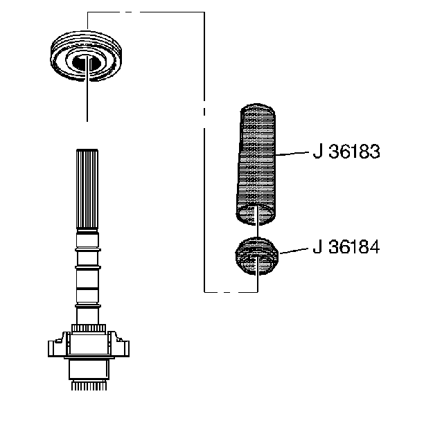
| 4.1. | Check the scribe marks for the correct positions. |
| 4.2. | Position the spiral lock ring towards the reverse speed gear. |
| 4.3. | Manually align and engage the splines. |
| 4.5. | Press the synchronizer until seated. |
| 4.6. | Remove all the metal shavings. |
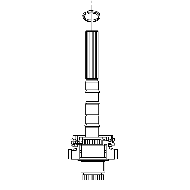
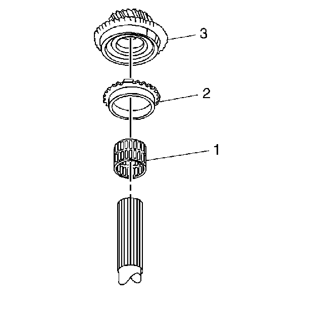
| 6.1. | The 5th speed gear needle bearing assembly |
| 6.2. | The synchronizer ring |
| 6.3. | The 5th speed gear |
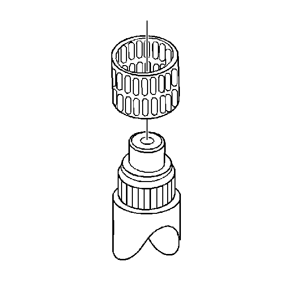
Important: The groove on the outside of the synchronizer sleeve must go towards the 2nd speed gear. This prevents gear clash during 1st and 2nd speed gear shifts. The teeth of the sleeve have different angles.
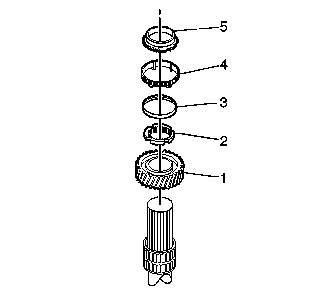
| 8.1. | The 1st speed gear |
| 8.2. | The synchronizer interim ring |
| 8.3. | The reaction cone |
| 8.4. | The blocker ring |
| 8.5. | The synchronizer cone |
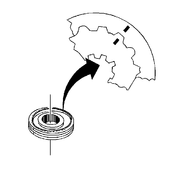
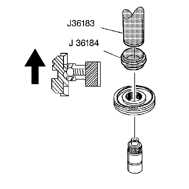
| 10.1. | Manually align and engage the splines. |
| 10.3. | Start the press operation. |
| • | Stop pressing before the tangs engage. |
| • | Lift and rotate the gear. |
| • | Engage the synchronizer ring. |
| 10.4. | Press the synchronizer until seated. |
| 10.5. | Remove all the metal shavings. |
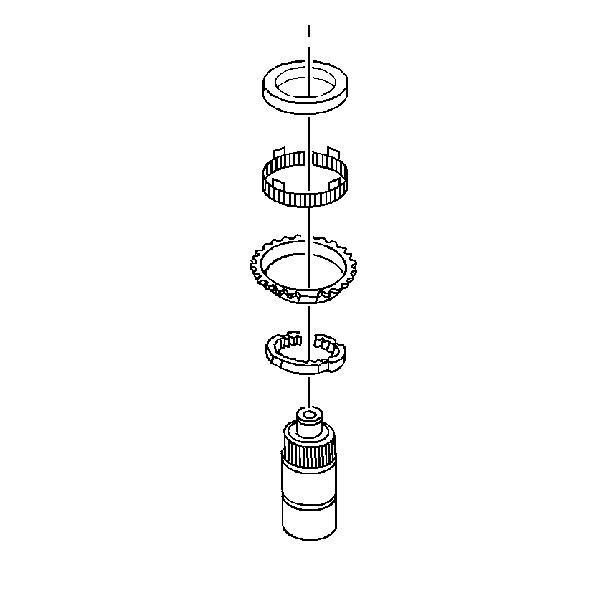
| 12.1. | The synchronizer cone |
| 12.2. | The blocker ring |
| 12.3. | The reaction cone |
| 12.4. | The interim ring |
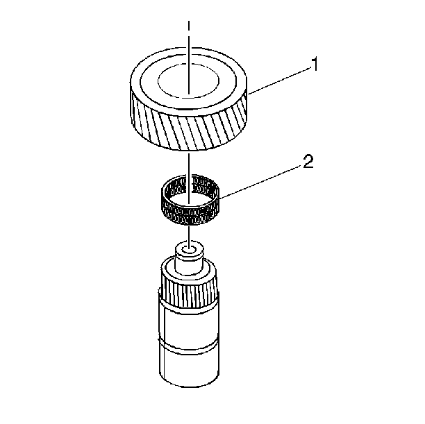
| 13.1. | The 2nd speed gear needle bearing assembly |
| 13.2. | The 2nd speed gear |
Make sure the bearing cage is together.
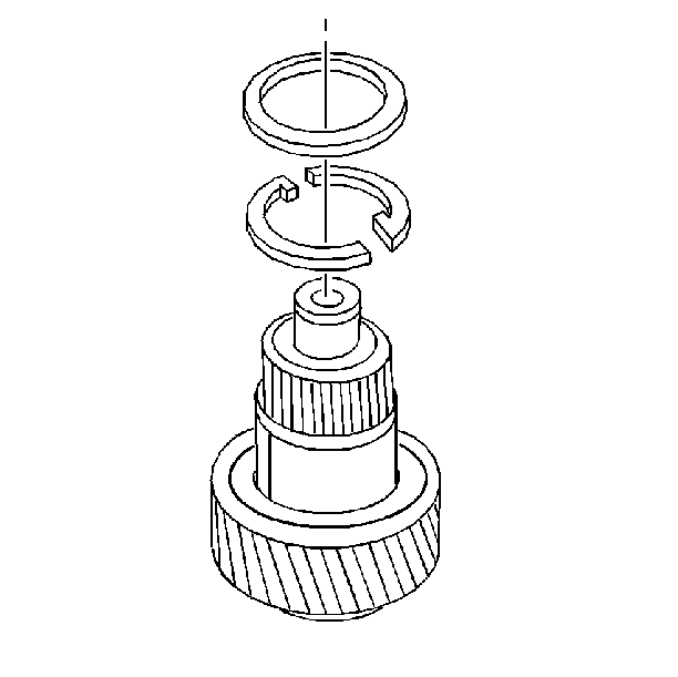
| 14.1. | The 2nd speed gear 2-piece thrust washer (Install the 2-piece thrust washers with the locating dots facing up.) |
| 14.2. | The retainer ring |
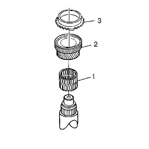
| 15.1. | The 3rd speed gear needle bearing assembly |
| 15.2. | The 3rd speed gear |
| 15.3. | The synchronizer ring |

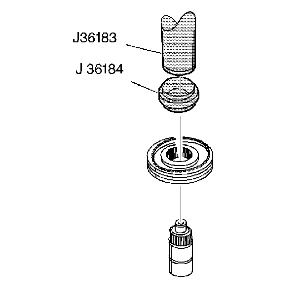
| 17.1. | Manually align and engage the splines. |
| 17.3. | Start the press operation. |
| 17.3.1. | Stop pressing before the tangs engage. |
| 17.3.2. | Lift and rotate the gear. |
| 17.3.3. | Engage the synchronizer ring. |
| 17.4. | Press the synchronizer until seated. |
| 17.5. | Remove all the metal shavings. |
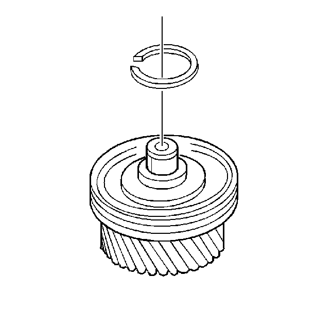
Main Shaft Assemble NV3500 RWD
Mainshaft Assembly
Tools Required
| • | Hydraulic Press |
| • | J 36183 Input Shaft Press Tube with Cap |
| • | J 36184 Adapter Press Tube Reducer |
| • | J 39924-1 Reverse Drag Seal Installer |
| • | J 39924-2 5th Speed Gear Drag Seal Installer |
- Install the 5th speed gear drag seal. Use J 39924-2 and J 36183 .
- Install the reverse speed gear drag seal. Use J 39924-1 .
- Install the following components:
- Install the 5th/Reverse speed gear synchronizer.
- Install a new mainshaft snap ring.
- Install the following components:
- Install the 1st speed gear needle bearing assembly
- Install the following components:
- Check the 1st/2nd speed gear synchronizer assembly scribe marks for correct positions.
- Install the 1st/2nd speed gear synchronizer assembly with both synchronizer rings.
- Install the following components:
- Install a new mainshaft snap ring.
- Install the following components:
- Install the following components:
- Install the following components:
- Check the 3rd/4th speed gear synchronizer assembly scribe marks for correct positions.
- Install the 3rd/4th speed gear synchronizer assembly with both synchronizer rings. Ensure that the groove in the synchronizer ring faces upward.
- Install a new mainshaft snap ring.
Important: Some components require an assembly lubricant. Use TRANSJEL or equivalent.


| 3.1. | The reverse speed gear needle bearing assembly |
| 3.2. | The reverse speed gear |

| 4.1. | Check the scribe marks for correct positions. |
| 4.2. | Position the spiral lock ring towards the reverse speed gear. |
| 4.3. | Manually align and engage the splines. |
| 4.5. | Press the synchronizer until seated. |
| 4.6. | Remove all the metal shavings. |


| 6.1. | The 5th speed gear needle bearing assembly |
| 6.2. | The synchronizer ring |
| 6.3. | The 5th speed gear |

Important: The groove on the outside of the synchronizer sleeve must go towards the 2nd speed gear. This prevents gear clash during 1st and 2nd speed gear shifts. The teeth of the sleeve have different angles.

| 8.1. | The 1st speed gear |
| 8.2. | The synchronizer interim ring with the teeth up |
| 8.3. | The reactor cone with the flat side towards 1st gear |
| 8.4. | The blocker ring with the teeth down |
| 8.5. | The synchronizer cone with the flat side down |


| 10.1. | Manually align and engage the splines. |
| 10.3. | Start the press operation. |
| 10.3.1. | Stop pressing before the tangs engage. |
| 10.3.2. | Lift and rotate the gear. |
| 10.3.3. | Engage the synchronizer ring. |
| 10.4. | Press the synchronizer until seated. |
| 10.5. | Remove all the metal shavings. |

| 11.1. | The synchronizer cone with the flat up |
| 11.2. | The blocker ring with the tangs up |
| 11.3. | The reaction cone with the wide flat portion up |
| 11.4. | The interim ring |


| 13.1. | The 2nd speed gear needle bearing assembly |
| 13.2. | The 2nd speed gear |
Ensure that the bearing cage is together. Ensure that the synchronizer ring gear teeth are toward 1st gear.

| 14.1. | The 2nd speed gear 2-piece thrust washer |
Ensure that the dots are facing up.
| 14.2. | The retainer ring |
Ensure that the retainer ring is installed around the washer.

| 15.1. | The 3rd speed gear needle bearing assembly |
| 15.2. | The 3rd speed gear |
| 15.3. | The synchronizer ring |


| 17.1. | Manually align and engage the splines. |
| 17.3. | Start the press operation |
| 17.3.1. | Stop pressing before the tangs engage. |
| 17.3.2. | Lift and rotate the gear. |
| 17.3.3. | Engage the synchronizer ring. |
| 17.4. | Press the synchronizer until seated. |
| 17.5. | Remove all the metal shavings. |

