For 1990-2009 cars only
Main Shaft Disassemble NV4500
Disassembly Procedure
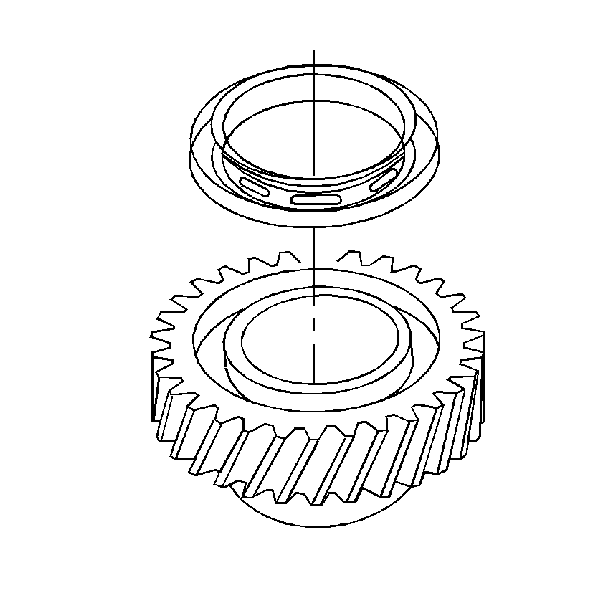
- Remove the 4TH speed gear clutch gear.
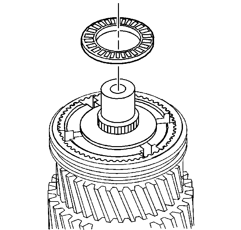
- Remove the main drive gear thrust bearing.
- Remove the 4TH speed gear synchronizer ring.
- Scribe a mark on the synchronizer hub and on the sleeve. This will help you to replace the parts in the same position.
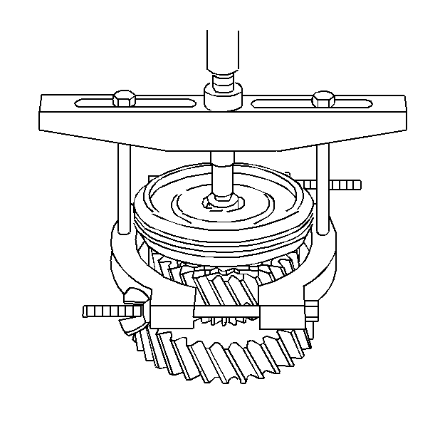
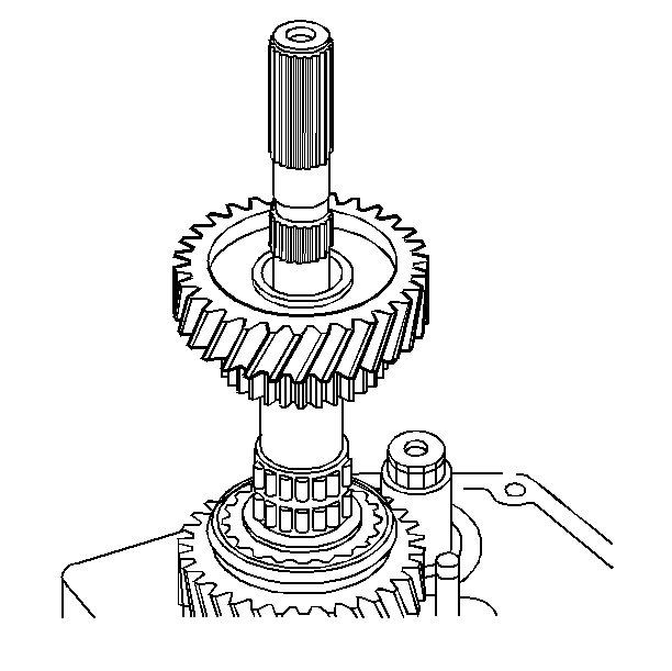
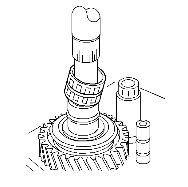
- Remove the 3RD speed gear and the 3--4 synchronizer assembly. Use a two-jaw puller. Place the puller jaws behind the 3RD speed gear clutching teeth.
- Remove the following parts:
- Remove the following parts
- Remove the 2ND speed gear.
- Remove the 2ND speed gear bearing.
- Remove the 2ND speed gear synchronizer retainer ring.
- Remove the 2ND speed gear synchronizer rings.
- Remove the 1--2 synchronizer sleeve retainer ring.
- Scribe a mark on the synchronizer hub and on the sleeve. This will help you to replace the parts in the same position.
- Remove the 1--2 synchronizer assembly.
- Remove the 1ST speed gear synchronizer retainer ring.
- Remove the following parts
- Turn the mainshaft over.
- Remove the rear mainshaft bearing. Use a hydraulic press and a suitable gear puller.
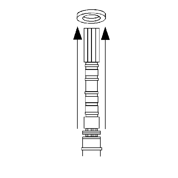
- Remove the reverse gear thrust washer.
- Scribe a mark on the synchronizer hub and on the sleeve. This will help you to replace the parts in the same position.
- Remove the reverse gear and synchronizer assembly from the mainshaft.
- Remove the reverse gear bearing and spacer.
- Remove the reverse gear clutch gear retainer ring.
- Remove the reverse gear synchronizer ring and the clutch gear.
- Remove the 1ST speed gear and the bearing.
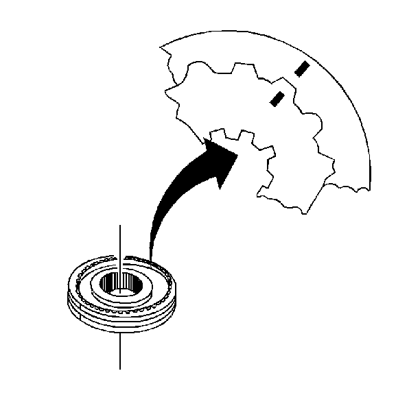
Important: Do not remove the sleeve from the synchronizer hub.
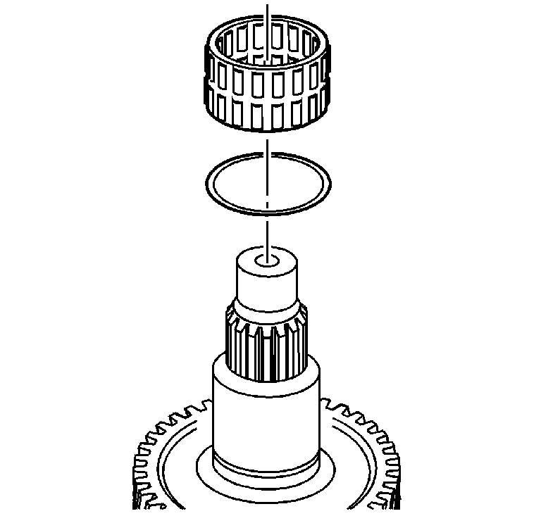
| 6.1. | The 3RD speed gear bearing |
| 6.2. | The spacer |
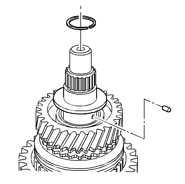
| 7.1. | The 2ND speed gear retainer ring |
| 7.2. | The thrust washer |
| 7.3. | The thrust washer retainer pin |
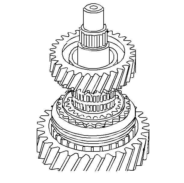
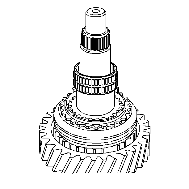
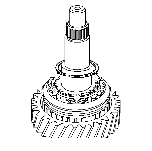
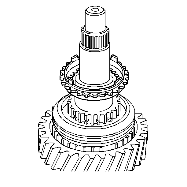
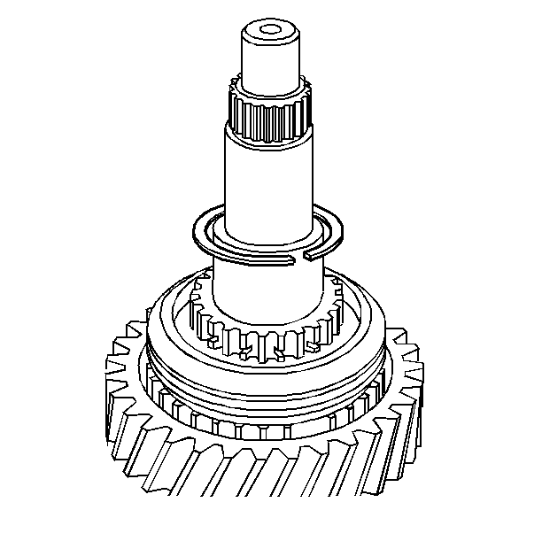

Important: Do not remove the sleeve from the synchronizer hub.
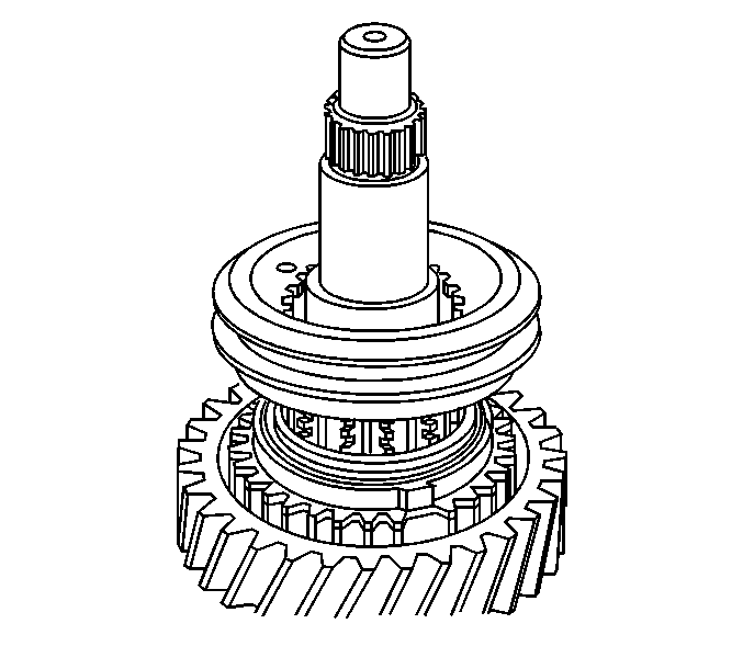
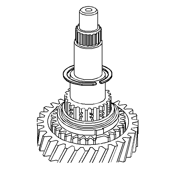
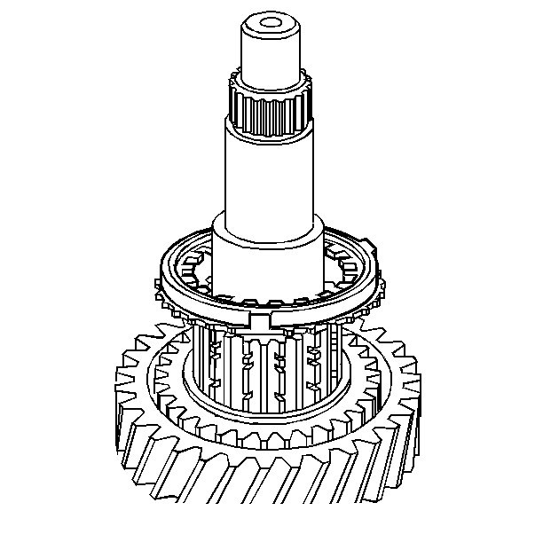
| 16.1. | The 1ST speed gear synchronizer rings |
| 16.2. | The clutch gear retainer ring |
| 16.3. | The clutch gear |
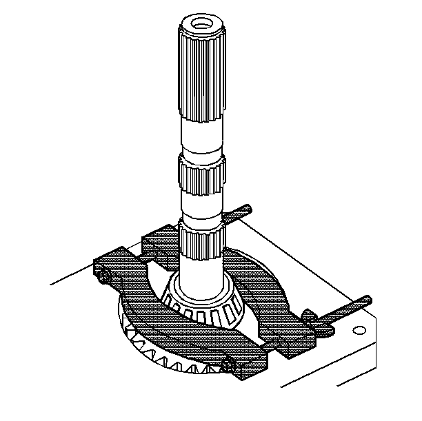
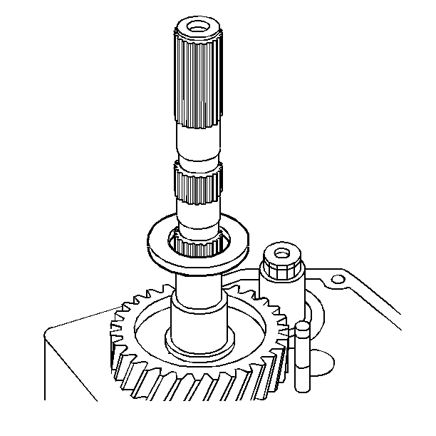

Important: Do not remove the sleeve from the synchronizer hub.
Main Shaft Disassemble NV3500 4WD
Mainshaft Disassembly
Tools Required
| • | Hydraulic Press |
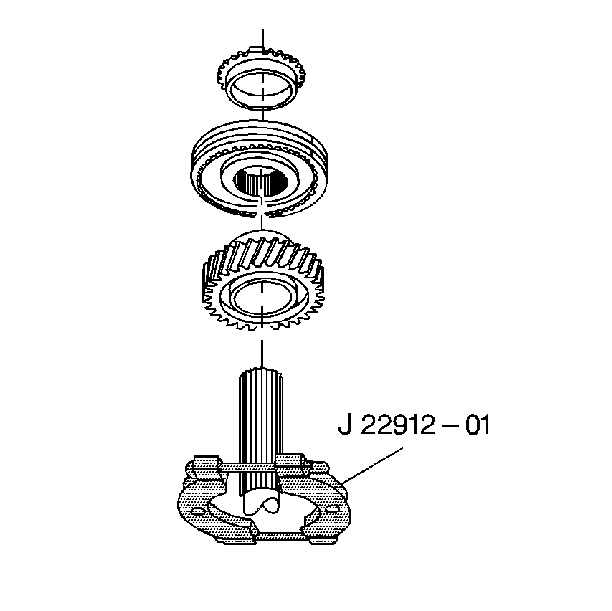
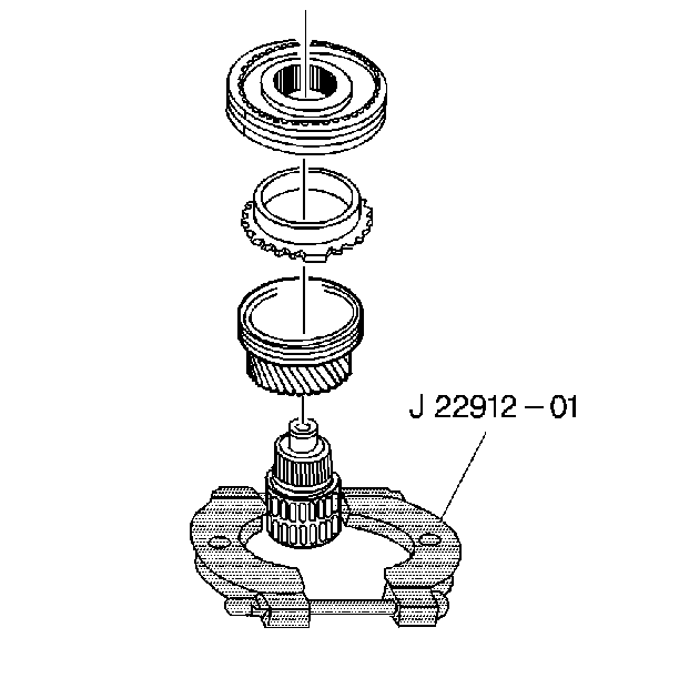
| • | J 22912-01 Gear and Bearing Separator Plate |
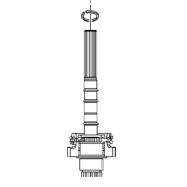
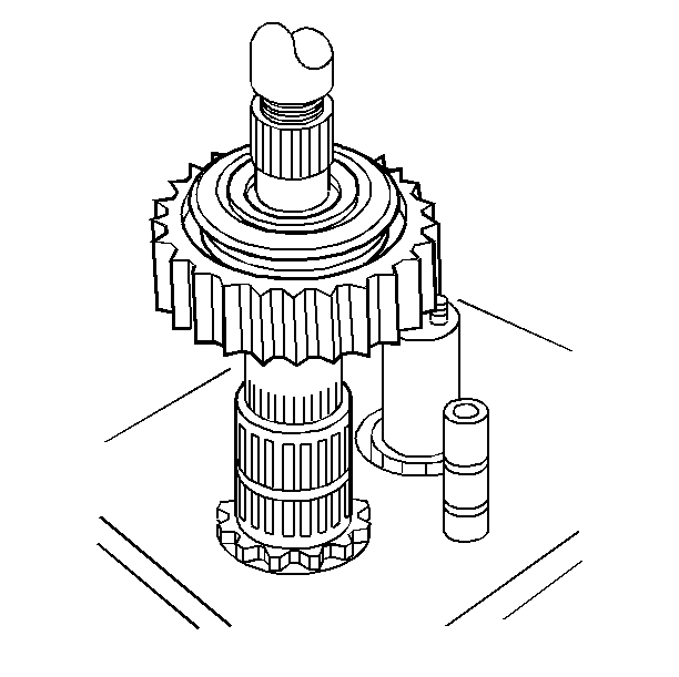
- Remove the mainshaft snap ring.
- Remove the 3rd/4th speed gear synchronizer and the 3rd speed gear. Use tool J 22912-01 and a hydraulic press.
- Scribe a mark on the synchronizer hub and on the sleeve. This will help you to reinstall the parts in the same position.
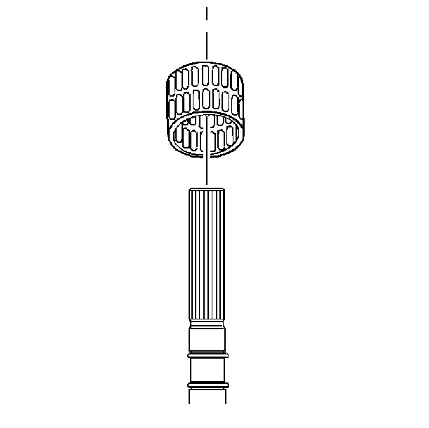
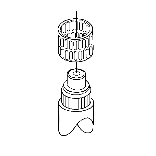
- Remove the 3rd speed gear needle bearing assembly.
- Remove the following components:
- Remove the 2nd speed gear.
- Remove the 2nd speed gear needle bearing assembly.
- Remove the following synchronizer parts:
- Remove the mainshaft snap ring.
- Remove the 1st speed gear and the 1st/2nd speed gear synchronizer.
- Scribe a mark on the synchronizer hub and on the sleeve. This will help you to reinstall the parts in the same position.
- Remove the following synchronizer parts:
- Remove the 1st speed gear needle bearing assembly.
- Remove the 5th speed gear.
- Remove the 5th speed gear needle bearing assembly.
- Remove the mainshaft snap ring.
- Remove the reverse speed gear and the 5th/Reverse speed gear synchronizer assembly. Use tool J 22912-01 and a hydraulic press.
- Scribe a mark on the synchronizer hub and on the sleeve. This will help you to reinstall the parts in the same position.
- Remove the reverse speed gear needle bearing assembly.
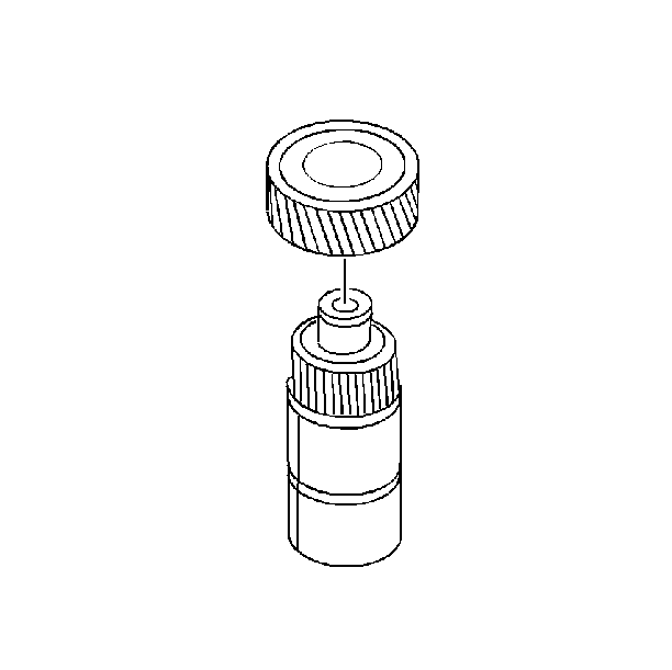
- Remove the drag seal from the mainshaft.
- Remove the drag seal from the reverse speed gear.
Important: Do not remove the sleeve from the synchronizer hub. The sleeve prevents the detent balls from popping out.
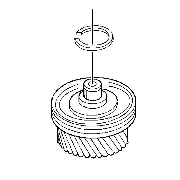

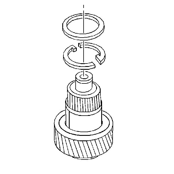
| 5.1. | The 2nd speed gear thrust washer retainer ring |
| 5.2. | The 2nd speed gear 2-piece thrust washer |
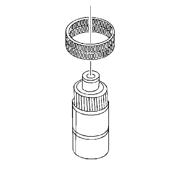
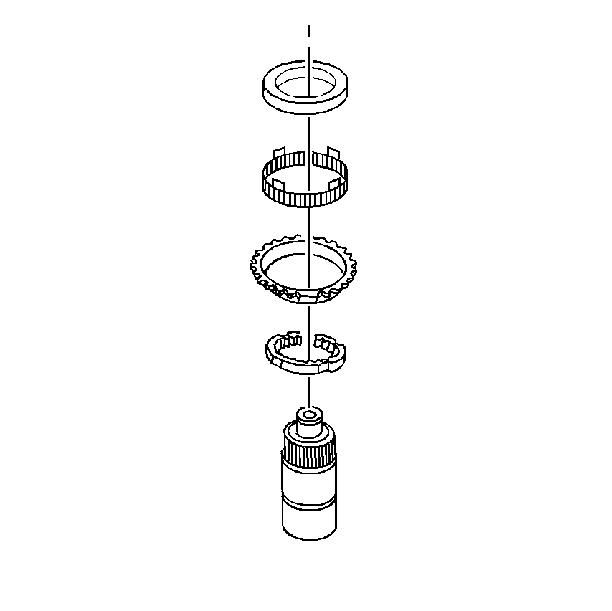
| 8.1. | The reaction cone |
| 8.2. | The synchronizer cone |
| 8.3. | The blocker ring |
| 8.4. | The interim ring |
Important: Do not remove the sleeve from the synchronizer hub. The sleeve prevents the detent balls from popping out.
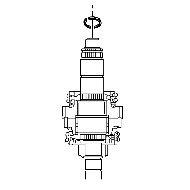
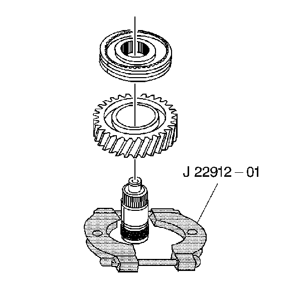
Use tool J 22912-01 and a hydraulic press.

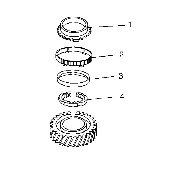
| 12.1. | The blocker ring (1) |
| 12.2. | The synchronizer cone (2) |
| 12.3. | The reaction cone (3) |
| 12.4. | The interim ring (4) |
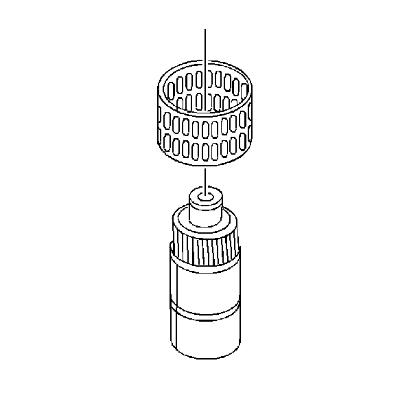
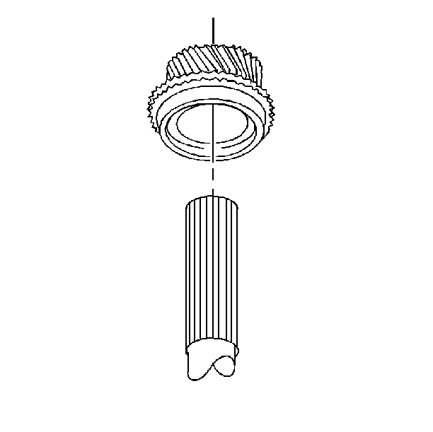
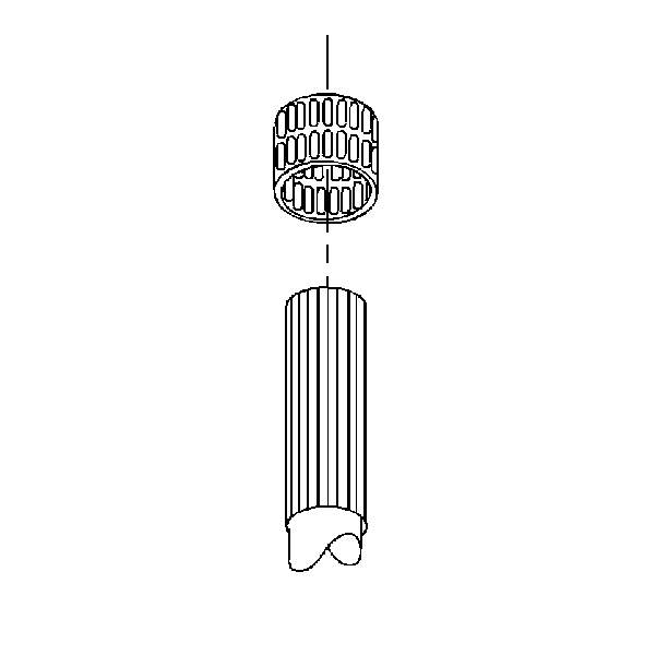
Important: Do not remove the sleeve from the synchronizer hub. The sleeve prevents the detent balls from popping out.
