Transmission Disassemble NV3500
Transmission Disassembly
Tools Required
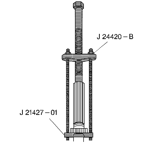
| • | J 21427-A Speedometer Gear Puller Adapter |
| • | J 23907 Slide Hammer |
| • | J 24420-B Gear Puller |
| • | J 26941 Output Shaft Oil Seal Remover |
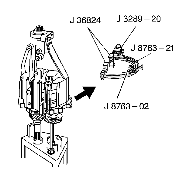
| • | J 3289-20 Base Holding Fixture |
| • | J 36509 Shift Shaft Detent Plug Remover |
| • | J 36515 Assembly Pallet |
| • | J 36515-15 Mainshaft Adapter |
| • | J 36515-16 Countershaft Adapter |
| • | J 36824 Transmission Adapters |
| • | J 8763-02 Holding Fixture C-Clamp |
| • | J 8763-21 Balance Bracket for C-Clamp |
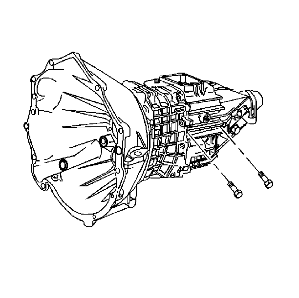
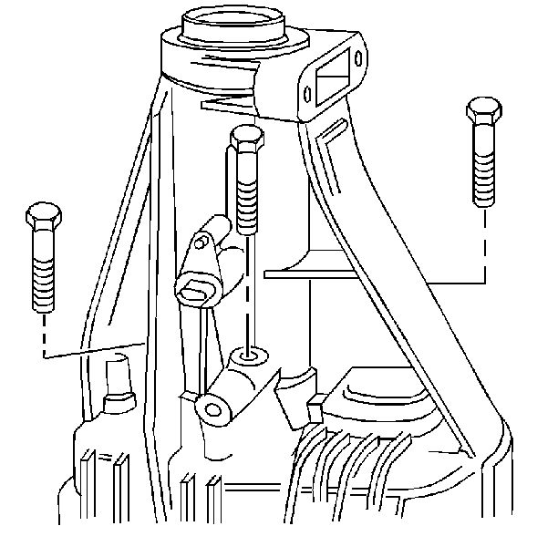
- Remove 2 reverse idler shaft support bolts.
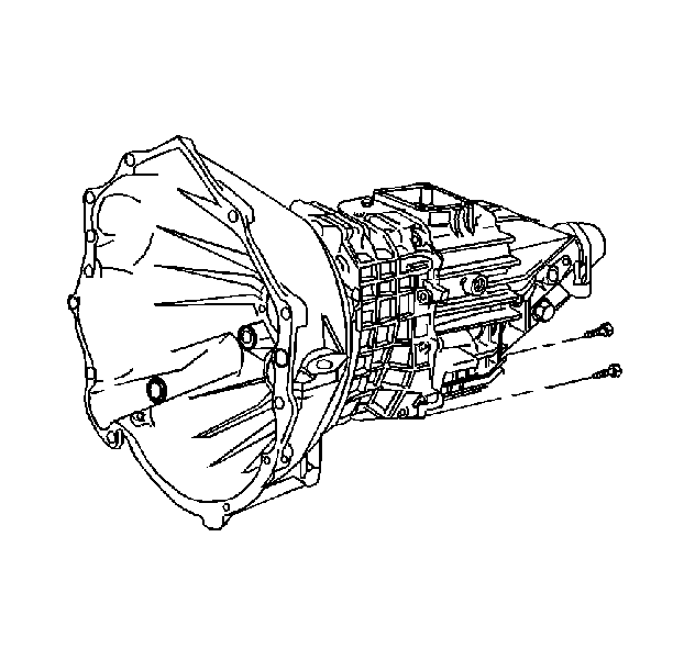
- Remove 2 lower-housing bolts. Tool J 3289-20 must be mounted securely on a sturdy workbench.
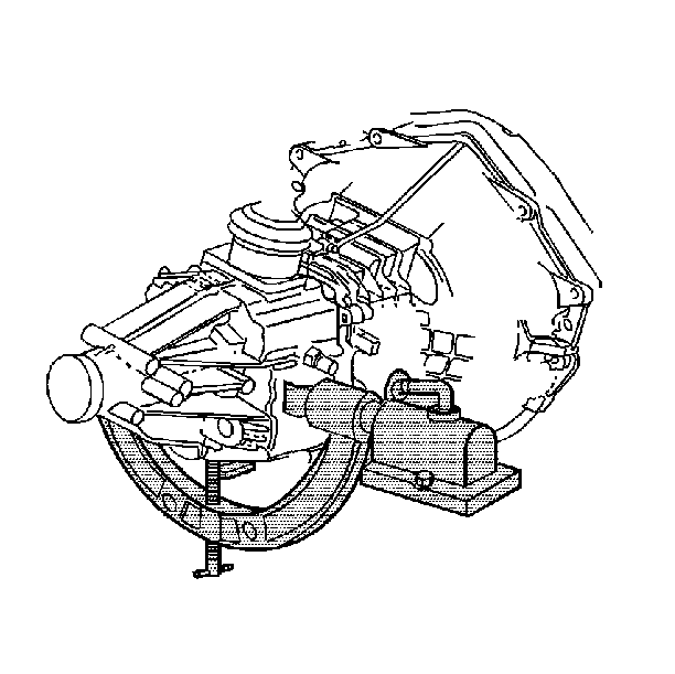
- Assemble the transmission holding fixture:
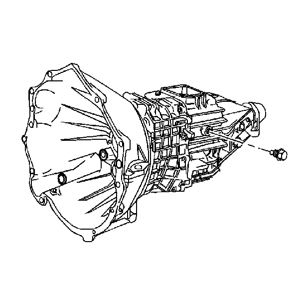
- Remove the backup lamp switch assembly.
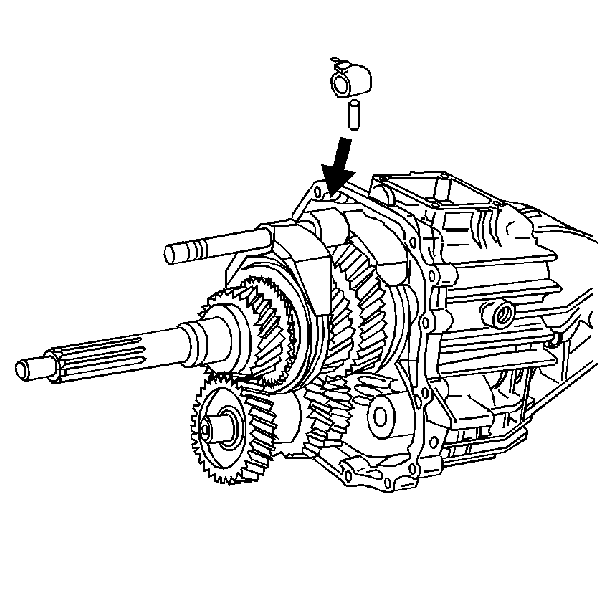
- Remove the shift shaft block-out bushing pin.
- Remove the following components:
- Complete the following tasks:
- Remove the concentric slave cylinder.
- Position the transmission vertically. Scribe the retainer and the case to aid in ensuring proper position during reassembly. Remove the following components:
- Remove the retainer by screwing two of the removed bolts into the threaded holes provided. Press off the retainer.
- Tap the clutch release bearing pilot with a rubber mallet.
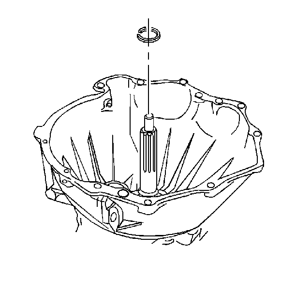
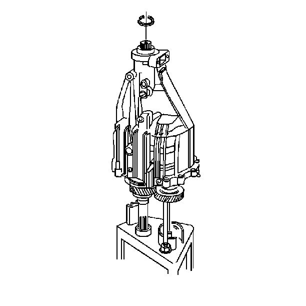
- Remove the input shaft snap ring.
- Position the transmission horizontally.
- Drive the 2 dowel pins into the front housing.
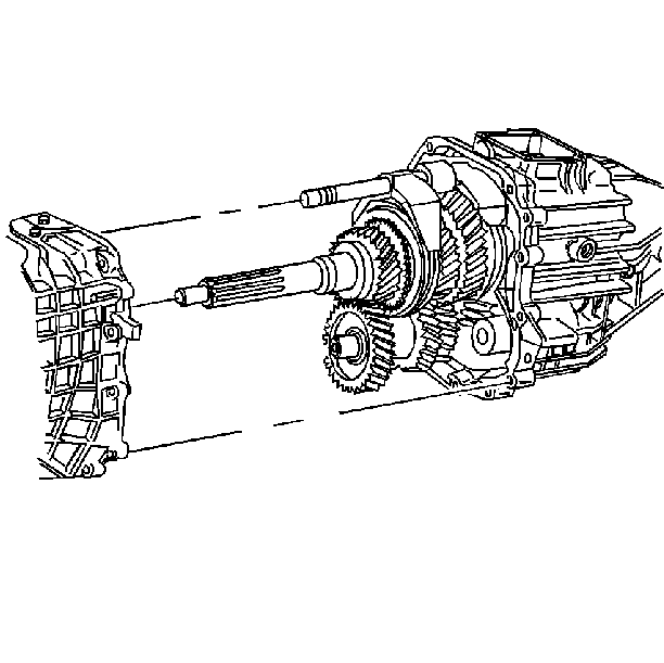
- Remove the front housing.
- Remove the countershaft bearing.
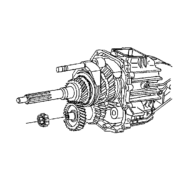
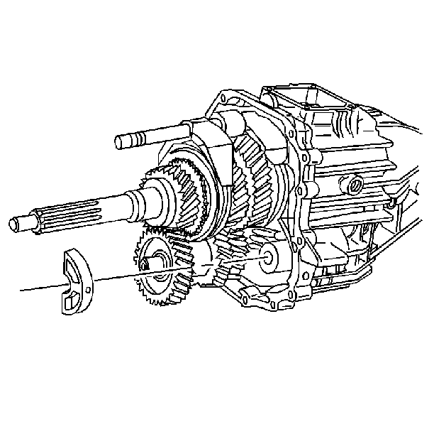
- Remove the reverse idler shaft support. The idler shaft support will snap out.
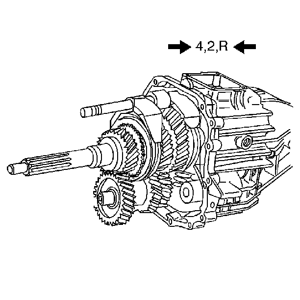
- Move all of the shift forks forward. Engage the 4th gear, the 2nd gear, and Reverse gear. Retain the shift lever detent plunger and spring.
- Remove the shift shaft lever roll pin.
- Shift all of the gears into neutral.
- Engage the 5th speed gear.
- Push the shift shaft into the housing.
- Remove the shift shaft socket roll pin.
- Remove the following components:
- Remove the 3rd/4th speed gear shift fork. Rotate counterclockwise
- Loosen 3 bolts on the rear of the housing. Do not remove the bolts.
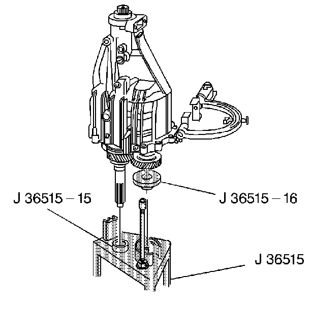
- Install the tool J 36515-15 on the input shaft.
- Install the tool J 36515-16 on the countershaft.
- Install the tool J 36515 to the transmission assembly.
- Place the unit fixture on the bench while holding the J 36515 fixture assembly on the transmission assembly.
- Remove tools J 8763-02 and J 36824 from the transmission housing.
- Remove the 3 bolts from the rear housing.
- Remove the rear housing. Tap the rear housing with a rubber mallet.
- Remove the mainshaft bearing retainer.
- Remove the following components:
- Partially lift the mainshaft to allow removal of the countershaft. Remove the following components:
- Remove the vehicle speed sensor reluctor wheel. Use the J 21427-A and the J 24420-B . Discard the reluctor wheel.
- Remove the following components:
- Remove the mainshaft assembly from the assembly pallet J 36515 . Remove the following parts:
| 3.2. | The J 36824 onto the transmission housing |
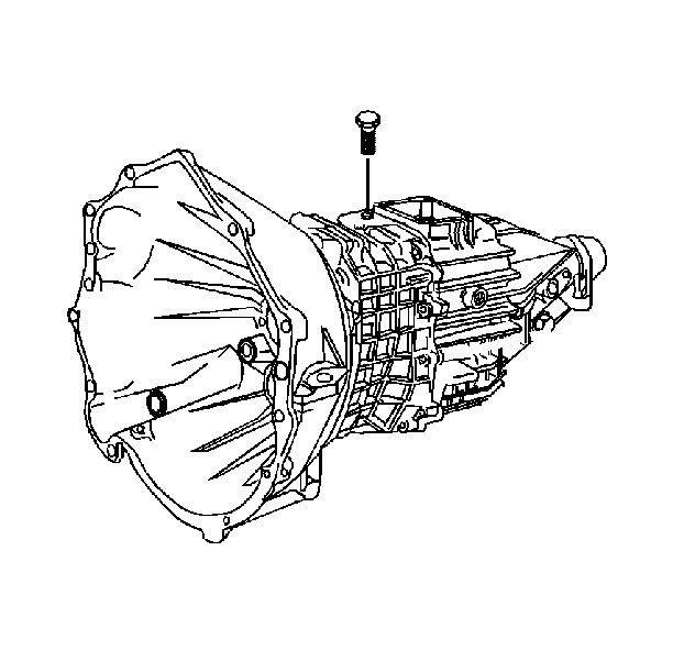
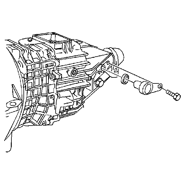
| 6.1. | The bolt |
| 6.2. | The vehicle speed sensor |
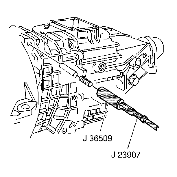
| 7.2. | Remove the detent spring and the detent plunger. |
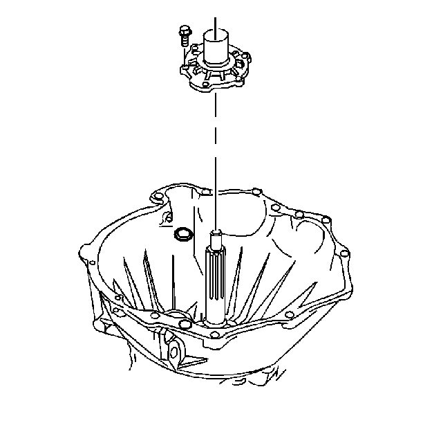
| 9.1. | The 6 bolts |
| 9.2. | The input shaft bearing retainer |
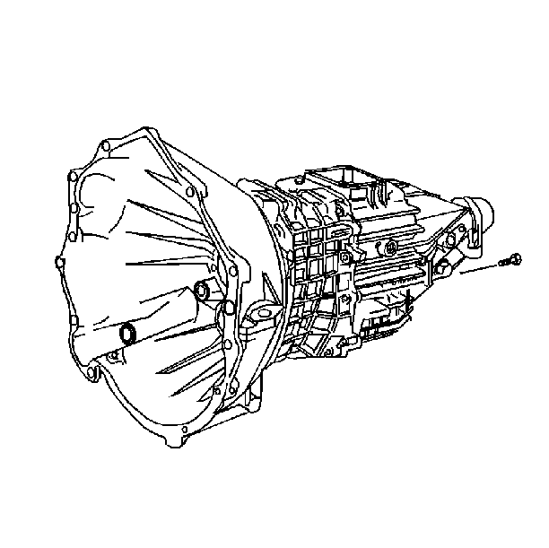
Remove the front housing to the rear housing bolts.
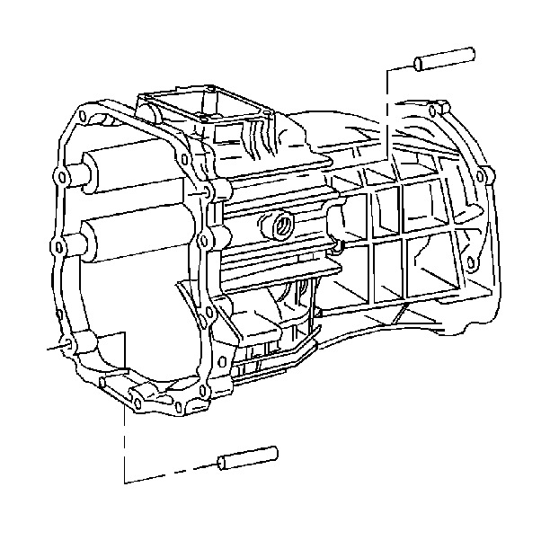
Important: Support the front housing. Do not allow the front housing to fall.
| 19.1. | Rotate the shift shaft lever finger down. |
| 19.2. | Support the shift shaft end. |
| 19.3. | Drive out the roll pin. |
| 19.4. | Ensure that the roll pin clears the 2nd speed gear. |
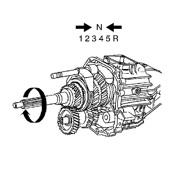
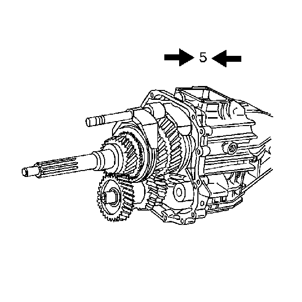
Notice: Excessive force peens the shift shaft and damages the shift shaft bearing. This causes increased shift effort.
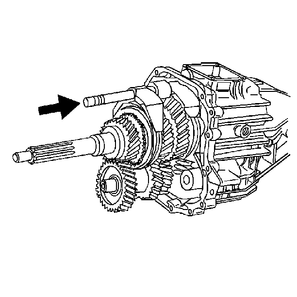
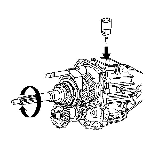
| 23.1. | Rotate the input shaft until a gap in the 5th speed/reverse speed synchronizer hub is directly under the roll pin. |
| 23.2. | Support the shift shaft end. |
| 23.3. | Drive out the roll pin. Use a 5 mm (3/16 in) punch. The roll pin will fall into the transmission housing. |
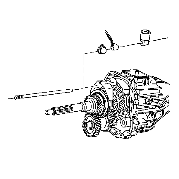
| 24.1. | The shift shaft |
| 24.2. | The shift shaft socket |
| 24.3. | The shift shaft lever |
| 24.4. | The shift shaft block-out bushing |
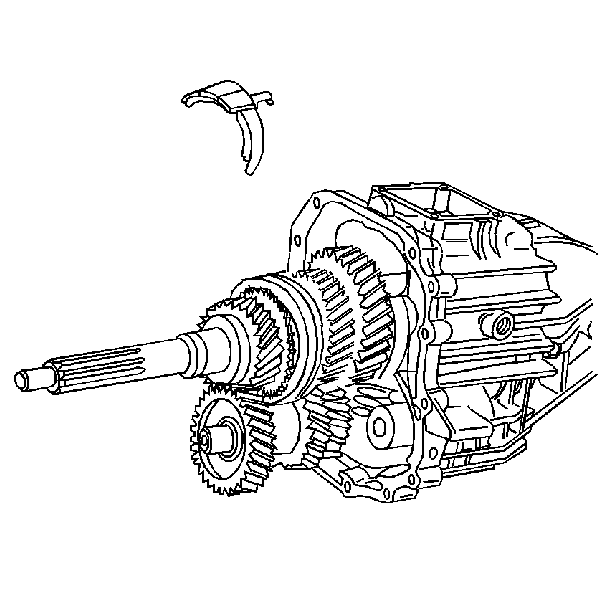
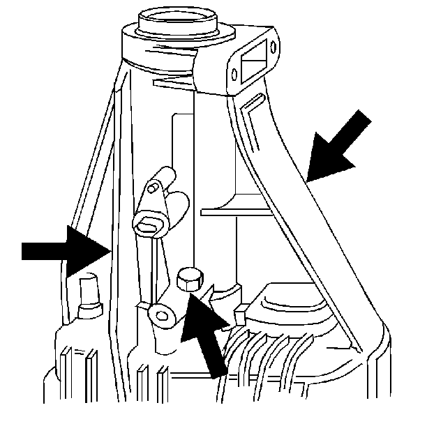
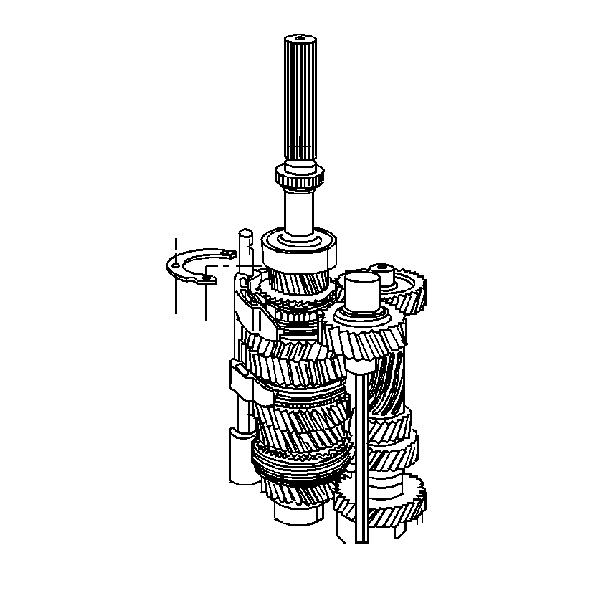
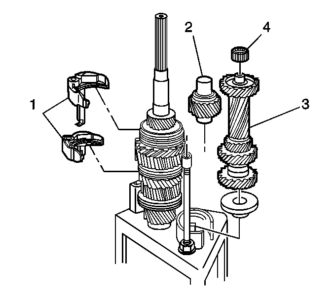
| 35.1. | 2 shift forks (1) |
| 35.2. | The reverse idler gear (2) |
| 36.1. | The countershaft (3) |
| 36.2. | The countershaft bearing (4) |
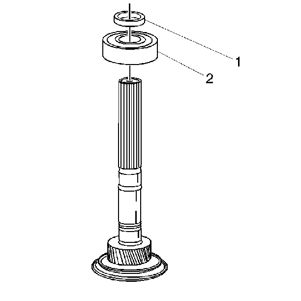
| • | The rear mainshaft bearing snap ring (1) |
| • | The rear mainshaft bearing (2) |
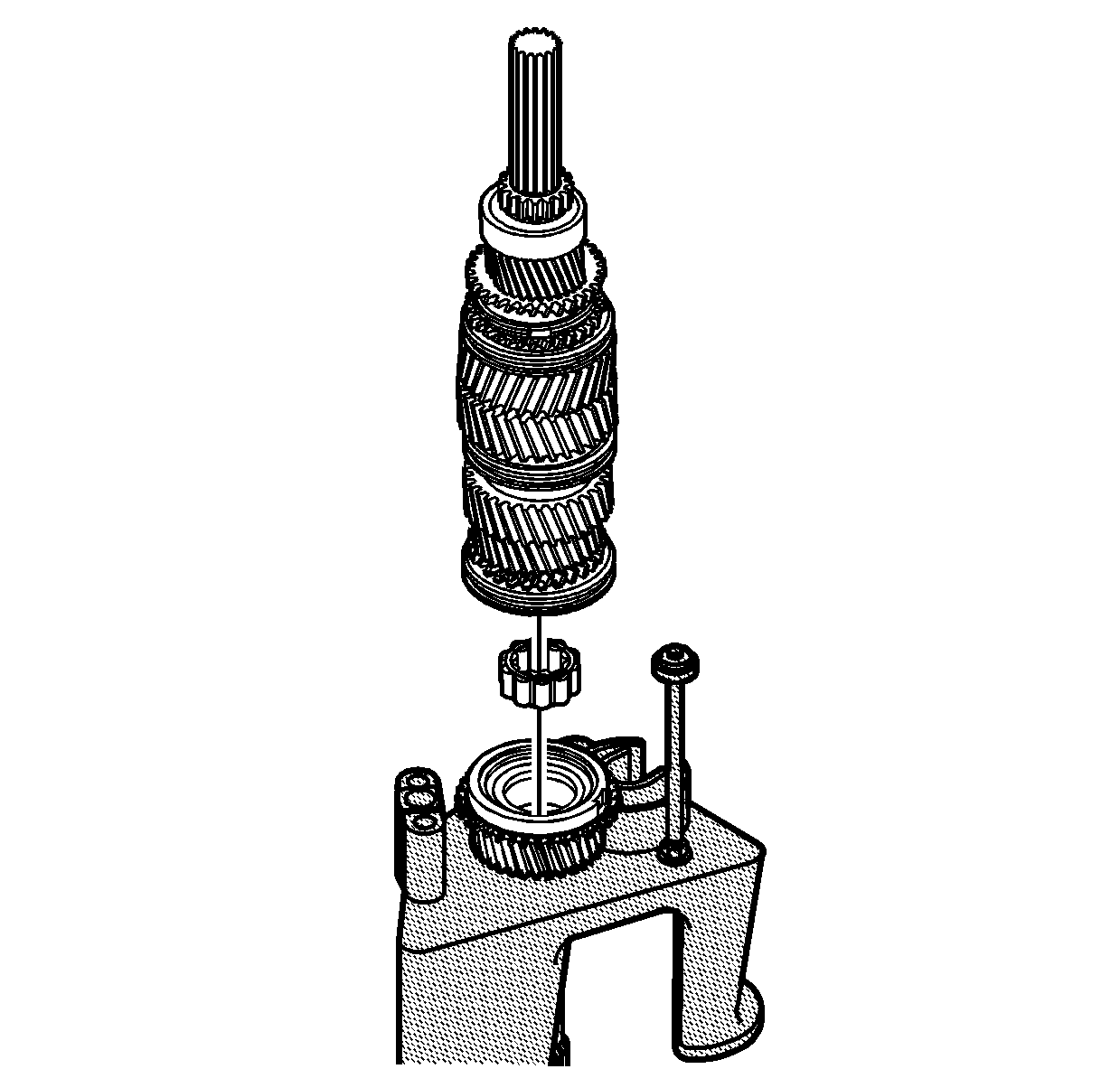
| • | The input shaft |
| • | The mainshaft pilot bearing from the input shaft |
Transmission Disassemble Four Wheel Drive
Transmission Disassembly
Tools Required
| • | J 23907 Slide Hammer with Pilot Bearing Puller |
| • | J 3289-20 Base Holding Fixture |
| • | J 36509 Detent Spring Plug Remover |
| • | J 36515 Assembly Pallet |
| • | J 36515-15 Mainshaft Adapter |
| • | J 36515-16 Countershaft Adapter |
| • | J 36824 Transmission Adapters |
| • | J 36825 4WD Output Shaft Oil Seal Remover |
| • | J 8763-02 Holding Fixture C-Clamp |
| • | J 8763-21 Balance Bracket for C-Clamp |
- Remove the two reverse idler shaft support bolts
- Remove two housing bolts
- Assemble the transmission holding fixture:
- Remove the backup lamp switch assembly.
- Remove the shift shaft block-out bushing pin.
- Remove the following components:
- Remove the output shaft oil seal. Use J 36825 and J 23907 .
- Position the transmission vertically. Remove the following components:
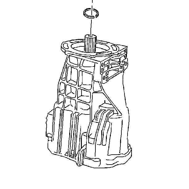
- Remove the input shaft snap ring.
- Position the transmission horizontally. Remove the front housing to the rear housing bolts.
- Drive the 2 dowel pins into the front housing.
- Remove the front housing.
- Remove the countershaft bearing.
- Remove the reverse idler shaft support. The idler shaft support will snap out.
- Move all the shift forks forward. Engage 4th gear, 2nd gear, and Reverse gear. Retain the shift lever detent plunger and spring.
- Remove the shift shaft lever roll pin.
- Shift all the gears into neutral.
- Engage the 5th speed gear.
- Push the shift shaft into the housing.
- Remove the shift shaft socket roll pin.
- Remove the following components:
- Remove the 3rd/4th speed gear shift fork. Rotate counterclockwise
- Install tool J 36515-15 on the input shaft.
- Install tool J 36515-16 on the countershaft.
- Install J 36515 to the transmission assembly with the adapters and transmission assembly upright on the work bench.
- Remove J 8763-02 and J 36824 from the transmission housing.
- Remove the mainshaft bearing snap ring.
- Remove the rear housing. Tap the rear housing with a rubber mallet.
- Remove the following components:
- Remove the mainshaft assembly from the assembly pallet J 36515 . Remove the following parts:


| 3.2. | J 36824 onto the transmission housing |
| 3.5. | Mount tool J 3289-20 securely on a sturdy workbench. |


| 6.2. | The detent spring |
| 6.3. | The detent plunger |
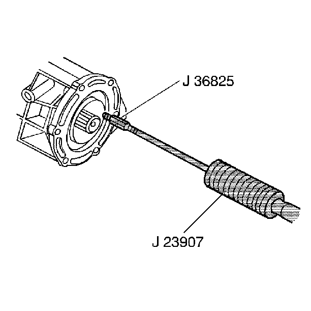
Use J 36825 by screwing it into one of the three perforated holes in the seal.

| 8.1. | The 6 bolts |
| 8.2. | The input shaft bearing retainer |
| 8.3. | Tap the clutch release bearing pilot with a rubber mallet. |


| 16.1. | Rotate the shift shaft lever finger down. |
| 16.2. | Support the shift shaft end. |
| 16.3. | Drive out the roll pin. |
| 16.4. | Ensure the roll pin clears the 2nd speed gear. |


Notice: Excessive force peens the shift shaft and damages the shift shaft bearing. This causes increased shift effort.


| 20.1. | Rotate the input shaft until a gap in the 5th speed/reverse speed synchronizer hub is directly under the roll pin. |
| 20.2. | Support the shift shaft end. |
| 20.3. | Drive out the roll pin. Use a 5 mm (3/16 in) punch. |
| 20.4. | The roll pin will fall into the transmission housing. |

| 21.1. | The shift shaft |
| 21.2. | The shift shaft socket |
| 21.3. | The shift shaft lever |
| 21.4. | The shift shaft block-out bushing |


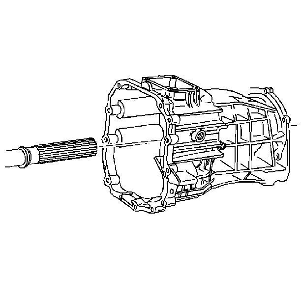

| 29.1. | Two shift forks (1) |
| 29.2. | The reverse idler gear (2) |
| 29.3. | The countershaft (3) |
| 29.4. | The countershaft bearing (4) |

| • | The input shaft |
| • | The mainshaft pilot bearing from the input shaft |
Transmission Disassemble NV4500
Disassembly Procedure
Tools Required
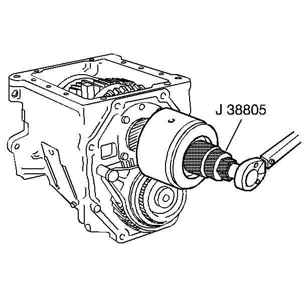
J 38805 Output Shaft Nut Socket (4WD only)
Important: Shift the transmission to neutral before beginning this procedure.
- Remove the shift tower to the shift cover bolts.
- Remove the shift tower from the shift cover.
- Remove the shift tower isolator plate from the shift cover.
- Remove the shift cover to the transmission case bolts. Pry the cover off by inserting screwdrivers in the slots provided. Note the location of the stud bolts.
- (RWD P-models, C-models and 4WD models) Shift the transmission into two gears in order to lock the output shaft.
- (RWD P-models) Remove the following parts:
- (RWD C-models) Remove the following parts:
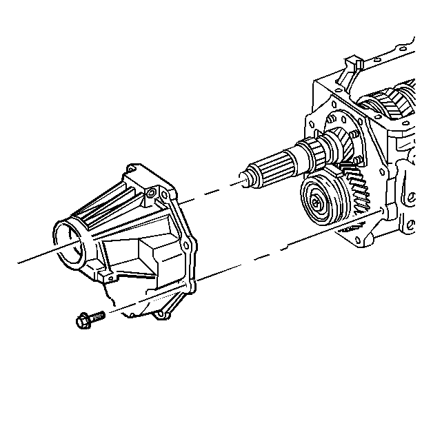
- (4WD models) Remove the rear oil retainer bolts. Strike the housing lightly with a soft-faced hammer. Pry off the housing.
- (RWD models) Remove the rear oil retainer bolts. Strike the housing lightly with a soft-faced hammer. Pry off the housing.
- (4WD models) Remove the mainshaft nut and the washer. Use the J 38805 .
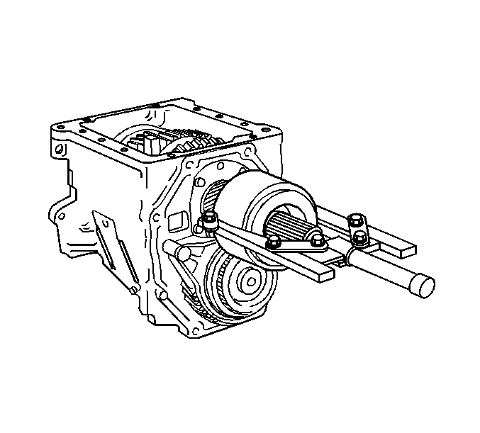
- (4WD models) Remove the vibration damper. Use a suitable gear puller.
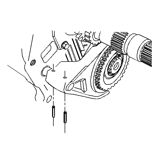
- Support the 5th gear shift fork. Drive out the 5th gear shift fork roll pins.
- Remove the 5th gear clutch gear retainer ring.
- Scribe a mark on the overdrive synchronizer hub and on the sleeve. This will help you to replace the parts in the same position.
- Remove the following parts:
- (RWD models) Use a puller to remove the mainshaft 5th gear and the vehicle speed sensor reluctor wheel. Note the direction that the mainshaft 5th gear and the vehicle speed sensor reluctor wheel are pressed onto the main shaft.
- Remove the following parts:
- Move the transmission to a horizontal position.
- Remove the mainshaft rear bearing cup:
- Mark the main drive gear bearing retainer and the case for alignment. Remove the main drive gear bearing retainer bolts. Drive the bearing retainer outward from inside the transmission case. Use a brass punch.
- Remove the main drive gear and the main drive gear bearing.
- Invert the transmission with the countershft plate upward.
- Remove the mainshaft assembly as follows:
- Remove the following parts:
- Remove the following parts:
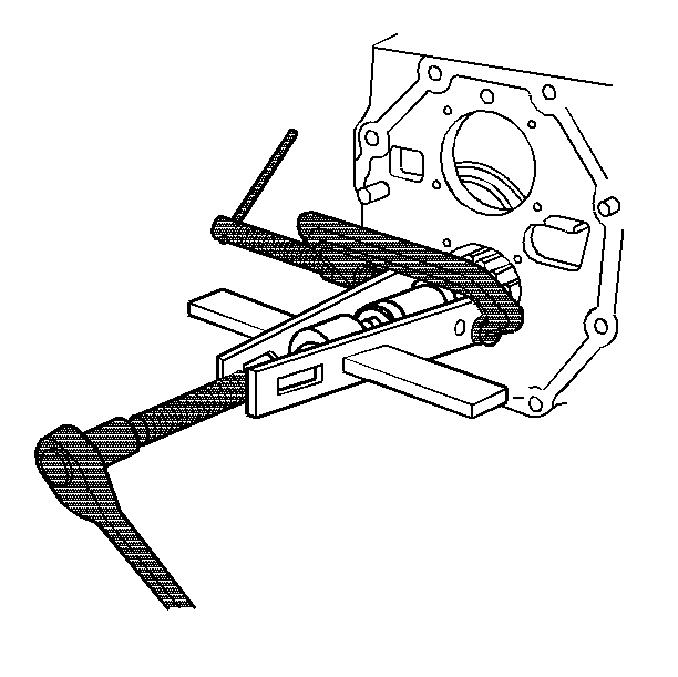
- Remove the countershaft rear bearing. Use a suitable bearing puller. Position the bearing puller behind the bearing inner race.
- Remove the countershaft assembly from the transmission case.
- Remove the countershaft bearing cap and the front bearing cup.
- Drive out the roll pin from the 5th gear shift lever. Remove the shift lever shaft. Push the shaft outward from inside the case. Remove the 5th gear shift lever from the shift lever shaft.
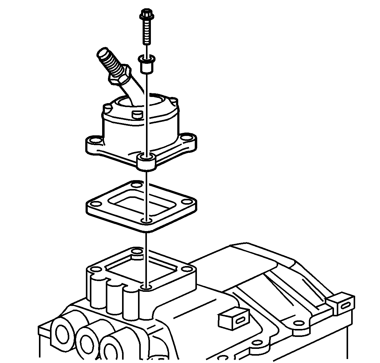
Important: Do not pry apart on the mating surfaces. The mating surfaces may be damaged.
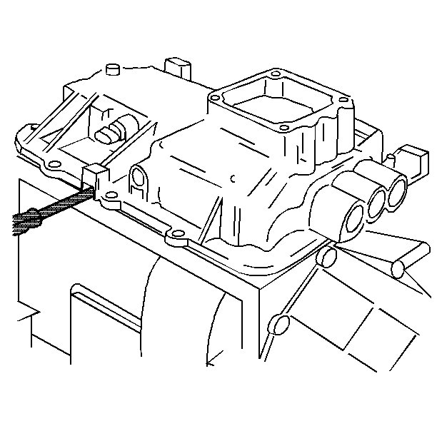
Important: Do not disassemble the shift cover. Individual components of the shift cover are not serviced. A damaged or worn shift cover must be replaced as a complete assembly.
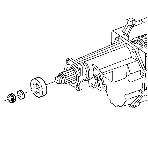
| 6.1. | The mainshaft nut |
| 6.2. | The washer |
| 6.3. | The spline seal |
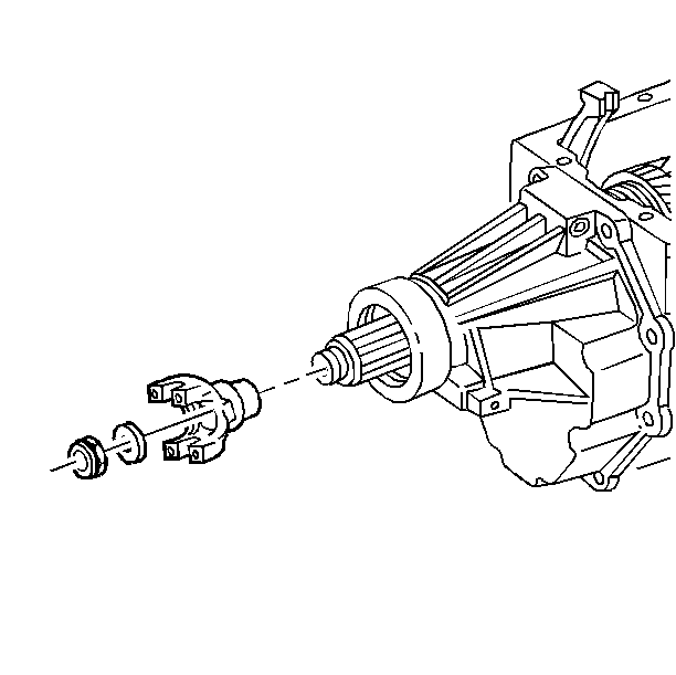
| 7.1. | The mainshaft nut |
| 7.2. | The washer |
| 7.3. | The yoke assembly |
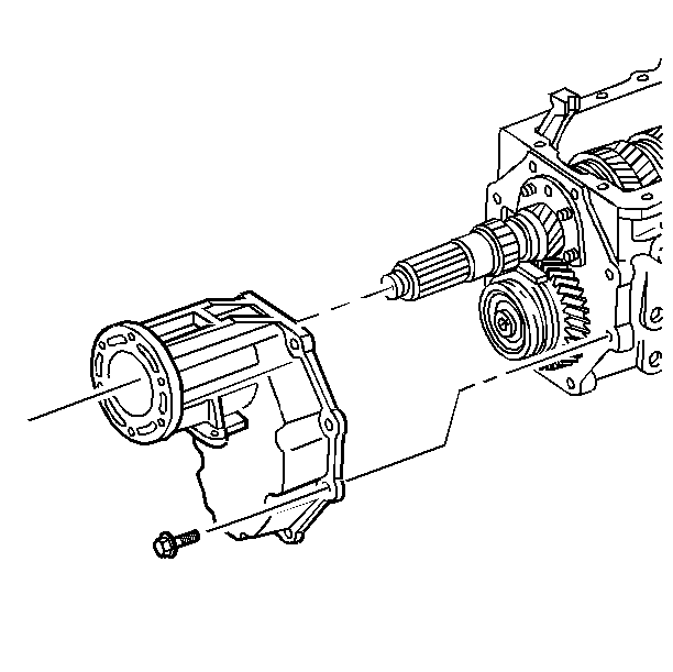
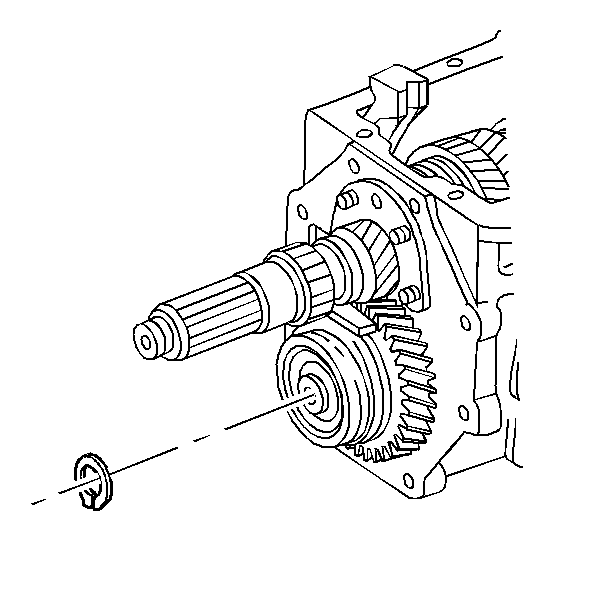
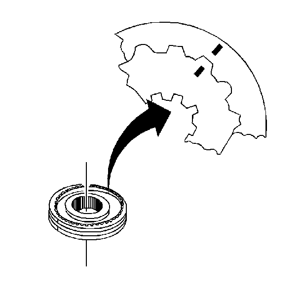
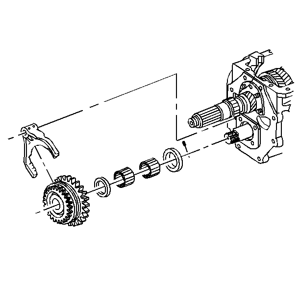
| 15.1. | The countershaft overdrive gear and the shift fork as an assembly (Do not let the synchronizer come apart. If necessary, remove the clutch gear, the synchronizer ring, the spacer, and the bearings. The overdrive gear will drop down for easy removal.) |
| 15.2. | The countershaft thrust washer |
| 15.3. | The pin |
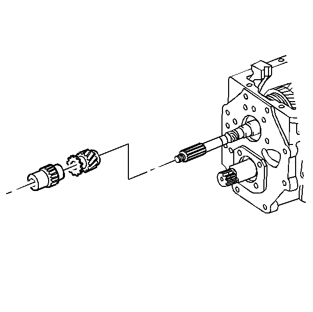
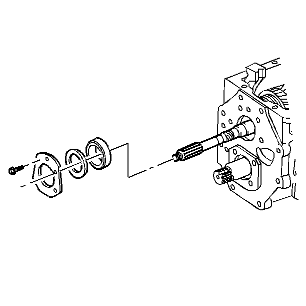
| 17.1. | The mainshaft rear bearing retaining plate bolts |
| 17.2. | The bearing retainer plate |
| 17.3. | The shim(s) |
| 19.1. | Move the synchronizer sleeves into neutral position. |
| 19.2. | Raise the fifth gear shift lever up out of the way and hold with a rubber band. |
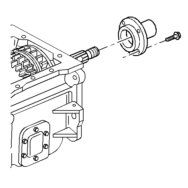
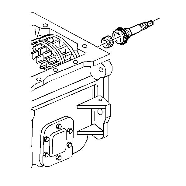
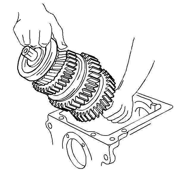
| 23.1. | Move the synchronizer sleeves into neutral position. |
| 23.2. | Raise the 5th gear shift lever up out of the way. Secure the lever with a rubber band. |
| 23.3. | Lift the mainshaft assembly by the nose through the front of the case. You may have to wiggle and twist the mainshaft assembly in order to disengage the second speed gear from the countershaft. |
| 23.4. | Remove the mainshaft assembly from the transmission case. |
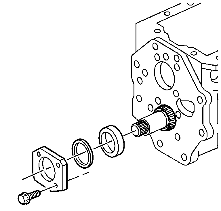
| 24.1. | The countershaft bearing retaining plate bolts |
| 24.2. | The bearing retainer plate |
| 24.3. | The shim(s) |
| 24.4. | The countershaft rear bearing cup |
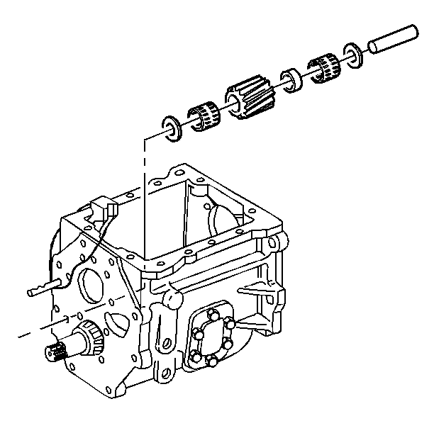
| 25.1. | The reverse idler gear shaft (Push the reverse idler shaft out from inside the transmission case.) |
| 25.2. | The reverse idler gear |
| 25.3. | The washers |
| 25.4. | The bearings |
| 25.5. | The spacer |
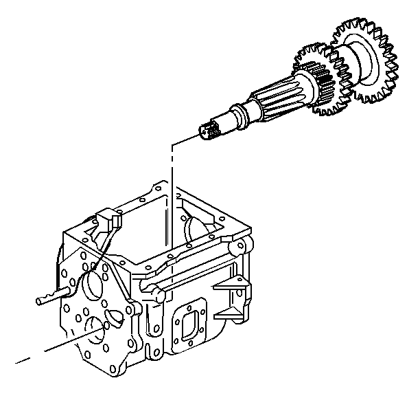

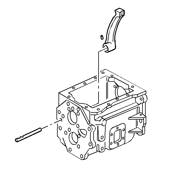
Important: Remove the 5th gear shift lever only if shifting into 5th gear is difficult.
