Transmission Replacement NV3500
Tools Required
J 36221 Quick Connect
Disengagement Tool
Removal Procedure
- Shift the transmission into 3RD or 4TH speed gear.
- Remove the shift lever and boot. Refer to
Shift Lever Replacement
.
- Raise the vehicle.
- Drain the transmission oil. Refer to
Fluid Replacement
.
- Remove the propeller shaft. Refer to Propeller Shaft Replacement
in Propeller Shaft.
- Remove the transfer case if the vehicle is equipped with four
wheel drive. Refer to Transfer Case Replacement in Transfer Case.
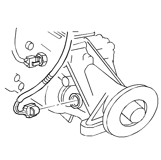
- Disconnect the wiring
harness connector from the vehicle speed sensor.
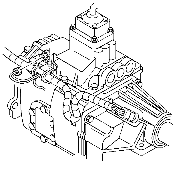
- Disconnect the wiring
harness connector from the backup lamp switch.
- Disconnect the wiring harness retainers from the transmission.
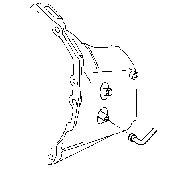
- Use the J 36221
. Depress the white plastic sleeve on
the quick connect in order to separate the hydraulic clutch line from the
concentric slave cylinder quick connect.
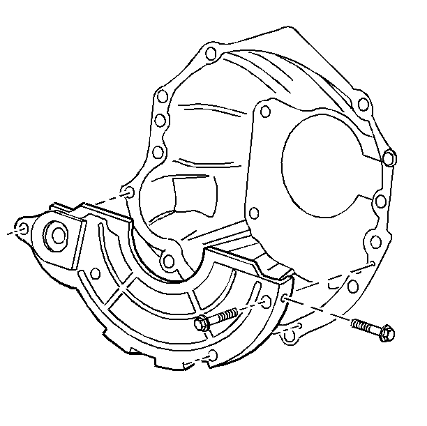
- Remove the clutch housing
cover.
- Remove the transmission rear mount.
- Support the transmission. Use a suitable safety stand.
- Remove the frame crossmember. Refer to Rear Bumper Brace Replacement
in Frame and Bumpers.
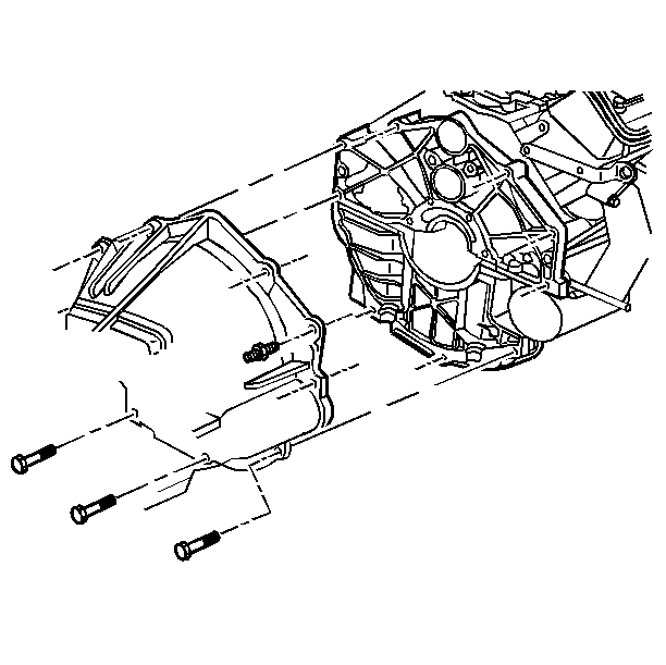
- Remove the transmission
to the clutch housing bolts and studs.
- Pull the transmission straight back on the clutch hub splines.
Do not let the transmission hang from the clutch plate and the clutch cover.
- Remove the transmission from the vehicle.
Installation Procedure

Important:
| • | Do not force the transmission into the clutch. |
| • | Do not let the transmission hang from the clutch. |
| • | Leave the safety stand under the transmission for support. |
- Install the transmission:
| 1.1. | Put a thin coat of high-temperature grease on the main drive gear
splines. |
| 1.2. | Shift the transmission into 3RD or 4TH speed gear. |
| 1.3. | Rotate the transmission clockwise onto the clutch hub splines. |
Notice: Use the correct fastener in the correct location. Replacement fasteners
must be the correct part number for that application. Fasteners requiring
replacement or fasteners requiring the use of thread locking compound or sealant
are identified in the service procedure. Do not use paints, lubricants, or
corrosion inhibitors on fasteners or fastener joint surfaces unless specified.
These coatings affect fastener torque and joint clamping force and may damage
the fastener. Use the correct tightening sequence and specifications when
installing fasteners in order to avoid damage to parts and systems.
| 1.4. | Install the bolts and the studs securing
the transmission to the engine. |
Tighten
Tighten the bolts to 47 N·m (35 lb ft).
- Install the frame crossmember. Refer to Rear Bumper Brace Replacement
in Frame and Bumpers.
- Install the transmission rear mount.
- Remove the safety stand from beneath the transmission.

- Install the hydraulic
clutch line to the concentric slave cylinder quick connect.
- Install the wiring harness retainers to the transmission.

- Install the electrical
connector to the backup lamp switch.

- Install the electrical
connector to the vehicle speed sensor.
- Install the transfer case if removed. Refer to Transfer Case Replacement
in Transfer Case.
- Install the propeller shaft. Refer to Propeller Shaft Replacement
in Propeller Shaft.
- Install the parking brake and controls, if removed. Refer to Parking
Brake Replacement in Parking Brake.
- Fill the transmission with new oil. Refer to
Fluid Replacement
.
- Remove the safety stands.
- Lower the vehicle.
- Install the shift lever and the boot. Refer to
Shift Lever Replacement
.
Transmission Replacement NV4500 RWD
Tools Required
J 36221 Clutch Line
Disconnect Tool
Removal Procedure
- Shift the transmission into 3RD or 4TH speed gear.
- Remove the transmission shift lever and the boot. Refer to
Shift Lever Replacement
.
- Raise the vehicle.
- Drain the transmission oil. Refer to
Fluid Replacement
.
- Remove the propeller shaft. Refer to Propeller Shaft Replacement
in Propeller Shaft.
- Remove the parking brake and controls, if used. Refer to Parking
Brake Replacement in Parking Brake.
- Disconnect the wiring harness connector from the backup lamp switch
and from the vehicle speed sensor.
- Disconnect the wiring harness retainers from the transmission.

- Disconnect the hydraulic
clutch line from the concentric slave cylinder using the J 36221
.
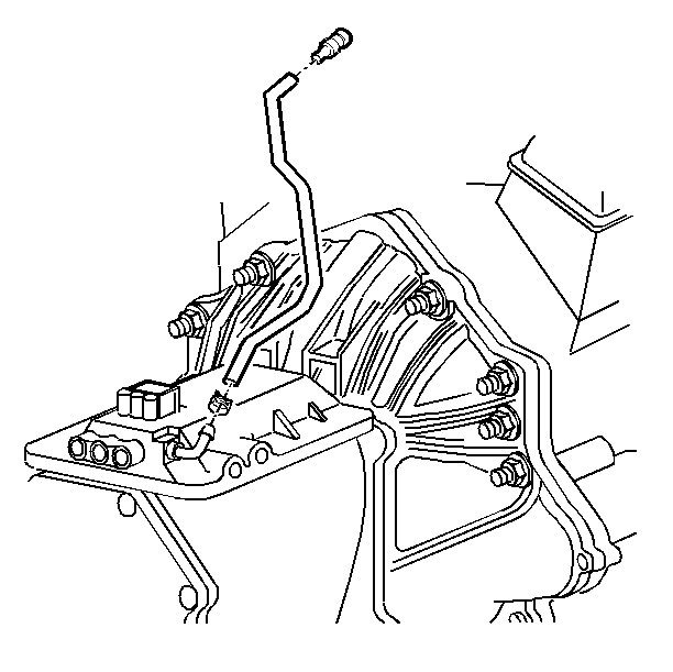
- Remove the transmission
vent hose from the transmission.
- Remove the transmission rear mount.
- Support the transmission.
- Remove the frame crossmember. Refer to Rear Bumper Brace Replacement
in Frame and Bumpers.
- Remove the transmission to engine bolts.
- Pull the transmission straight back on the clutch hub splines.
Do not let the transmission hang from the clutch plate and clutch cover.
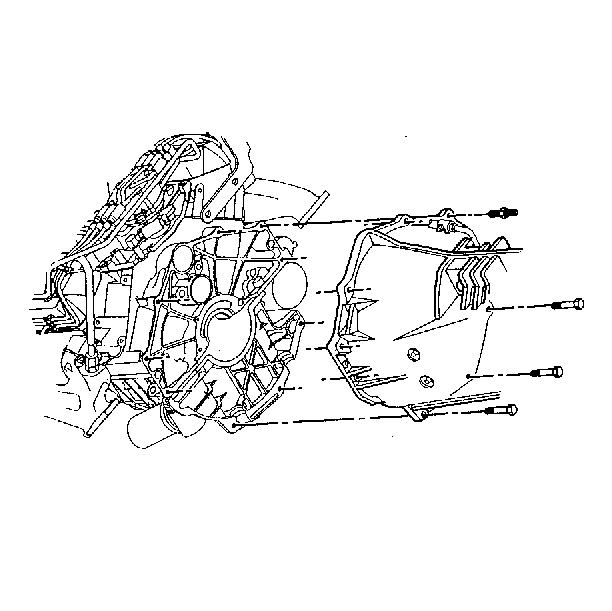
- Remove the transmission
from the vehicle.
Installation Procedure

Important:
| • | Do not force the transmission into the clutch. |
| • | Do not let the transmission hang from the clutch. |
| • | Leave the safety stand under the transmission for support. |
- Install the transmission.
| 1.1. | Put a thin coat of high-temperature grease on the main drive gear
splines. |
| 1.2. | Shift the transmission into 3RD or 4TH speed gear. |
| 1.3. | Rotate the transmission clockwise onto the clutch hub splines. |
Notice: Use the correct fastener in the correct location. Replacement fasteners
must be the correct part number for that application. Fasteners requiring
replacement or fasteners requiring the use of thread locking compound or sealant
are identified in the service procedure. Do not use paints, lubricants, or
corrosion inhibitors on fasteners or fastener joint surfaces unless specified.
These coatings affect fastener torque and joint clamping force and may damage
the fastener. Use the correct tightening sequence and specifications when
installing fasteners in order to avoid damage to parts and systems.
| 1.4. | Install the transmission to the engine
bolts and washers. |
Tighten
Tighten the bolts to 100 N·m (74 lb ft).
- Install the transmission to engine bolts.
Tighten
Tighten the studs to 31 N·m (23 lb ft).
- Install the frame crossmember. Refer to Rear Bumper Brace Replacement
in Frame and Bumpers.
- Install the transmission rear mount.
- Remove the safety stand from beneath the transmission.

- Install the transmission
vent hose.

- Install the hydraulic
clutch line to the concentric slave cylinder quick connect.
- Install the wiring harness retainers to the transmission.
- Connect the following electrical wiring harness connectors:
| • | The vehicle speed sensor |
- Install the propeller shaft. Refer to Propeller Shaft Replacement
in Propeller Shaft.
- Install the parking brake and controls, if removed.
Refer to Parking Brake Replacement in Parking Brake.
- Fill the transmission with new oil. Refer to
Fluid Replacement
.
- Remove the safety stands.
- Lower the vehicle.
- Install the shift lever and the boot. Refer to
Shift Lever Replacement
.
Transmission Replacement NV4500 4WD
Tools Required
J 36221 Quick Connect
Disengagement Tool
Removal Procedure
- Shift the transmission into 3RD or 4TH speed gear.
- Remove the shift lever. Refer to
Shift Lever Replacement
.
- Drain the transmission oil. Refer to
Fluid Replacement
.
- Remove the propeller shaft. Refer to Propeller Shaft Replacement
in Propeller Shaft.
- Remove the transfer case. Refer to Transfer Case Replacement
in Transfer Case.
- Remove the parking brake and controls, if used. Refer to Parking
Replacement in Parking Brake.
- Disconnect the following electrical wiring harness connectors:
| • | The vehicle speed sensor |
- Disconnect the wiring harness retainers from the transmission.

- Disconnect the hydraulic
clutch line from the concentric slave cylinder using the J 36221
.

- Remove the transmission
vent hose.
- Remove the transmission rear mount.
- Support the transmission. Use a suitable safety stand.
- Remove the frame crossmember. Refer to Rear Bumper Brace Replacement
in Frame and Bumpers.

- Remove the transmission
to engine bolts.
- Pull the transmission straight back on the clutch hub splines.
Do not let the transmission hang from the clutch plate and clutch cover.
- Remove the transmission from the vehicle.
Installation Procedure

Notice: Use the correct fastener in the correct location. Replacement fasteners
must be the correct part number for that application. Fasteners requiring
replacement or fasteners requiring the use of thread locking compound or sealant
are identified in the service procedure. Do not use paints, lubricants, or
corrosion inhibitors on fasteners or fastener joint surfaces unless specified.
These coatings affect fastener torque and joint clamping force and may damage
the fastener. Use the correct tightening sequence and specifications when
installing fasteners in order to avoid damage to parts and systems.
- Install the clutch housing to the engine,
if removed.
Tighten
Tighten the studs to 100 N·m (74 lb ft).
Important:
| • | Do not force the transmission into the clutch. |
| • | Do not let the transmission hang from the clutch. |
| • | Leave the safety stand under the transmission for support. |
- Install the transmission.
| 2.1. | Put a thin coat of high-temperature grease on the main drive gear
splines. |
| 2.2. | Shift the transmission into 3RD or 4TH speed gear. |
| 2.3. | Rotate the transmission clockwise onto the clutch hub splines. |
Notice: Use the correct fastener in the correct location. Replacement fasteners
must be the correct part number for that application. Fasteners requiring
replacement or fasteners requiring the use of thread locking compound or sealant
are identified in the service procedure. Do not use paints, lubricants, or
corrosion inhibitors on fasteners or fastener joint surfaces unless specified.
These coatings affect fastener torque and joint clamping force and may damage
the fastener. Use the correct tightening sequence and specifications when
installing fasteners in order to avoid damage to parts and systems.
| 2.4. | Install the transmission to the clutch
housing bolts and washers. |
Tighten
Tighten the bolts to 31 N·m (23 lb ft).
- Install the frame crossmember. Refer to Rear Bumper Brace Replacement
in Frame and Bumpers.
- Install the transmission rear mount.
- Remove the safety stand from beneath the transmission.

- Install the transmission
vent hose.

- Install the hydraulic
clutch line to the concentric slave cylinder quick connect.
- Install the wiring harness retainers to the transmission.
- Connect the following electrical wiring harness connectors:
| • | The vehicle speed sensor |
- Install the transfer case. Refer to Transfer Case Replacement
in Transfer Case.
- Install the propeller shaft. Refer to Propeller Shaft Replacement
in Propeller Shaft.
- Install the parking brake and controls, if removed. Refer to Parking
Brake Replacement in Parking Brake.
- Fill the transmission with new oil. Refer to
Fluid Replacement
.
- Remove the safety stands.
- Lower the vehicle.
- Install the shift lever to the transmission. Refer to
Shift Lever Replacement
.


