Frame Bracket Knock Out Removal C Model
Removal Procedure
Tools Required
J 38794 Knockout
Removal Tool
Important: As originally installed, the upper control arm cannot be adjusted for
the caster or the camber. However, if the caster or the camber is measured
and is out of tolerance, the caster and the camber can be set to
the proper specifications.
- Raise the vehicle.
- Suitably support the vehicle. Refer to
Lifting and Jacking the Vehicle
in General Information.
Important: The jack or the jack stand must remain under the lower control arm during
the removal and the installation procedure in order to retain the lower control
arm position.
- Support the lower control arms with a jack or the jack stands.
- Remove the tire and the wheel assembly.

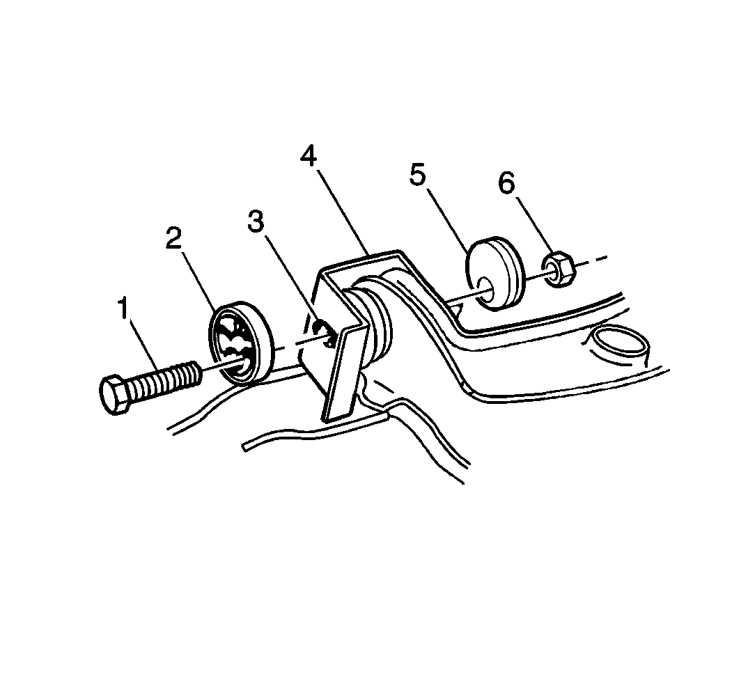
- Remove the following parts
from the upper control arm bracket (4):

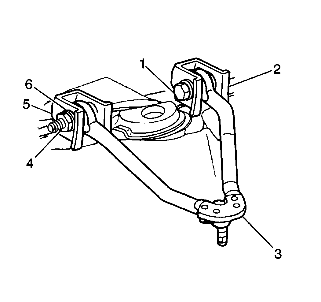
- Lift the upper control
arm (3) up and to the side in order to gain access to the inner portion of
the frame bracket.
- Use the J 38794
in
order to remove the frame bracket knockout as follows:
| • | Do not distort the frame bracket when removing the knockout. |
| • | Apply extreme pressure lubricant to the threads of the T-bolt. |
| • | Insert the bolt through the knockout hole in the bracket support. |
| • | Install the bridge onto the T-bolt. |
| • | The forward bracket requires the bridge to be installed between the
legs of the bracket due to access problems. |
| | Notice: Do not subject the tool to more than 100 N·m (75 lb ft)
torque. Exceeding the recommended torque may damage the tool and/or the bracket.
|
| • | Assemble the following parts in order: |
| 2. | The bearing with the chamfered side out |
| • | The T-bolt head and the bridge must line up horizontally with
the knockout. |
| • | The bridge should span the knockout without interfering with the knockout
procedure. |
| • | Tighten the T-bolt head against the knockout by turning the nut
at the opposite end using a socket and torque wrench. |
| • | An open end wrench or adjustable wrench may be needed in order
to prevent the T-bolt from losing the horizontal alignment with the knockout. |
| • | If the torque limit on the T-bolt is met and the knockout does
not break free, use a die grinder of appropriate size. |
| • | Using the stamped outline as a guide, remove the knockout. |
| • | Remove the wax coating in the knockout area in order to make the perforation
lines more visible. |
| • | If the outline is not visible, use the T-bolt head installed horizontally,
as a template, and scribe the frame bracket. |
| • | Repeat the procedure on the other upper control arm frame bracket. |
Installation Procedure

- Install the upper control
arm (3) into the frame brackets (2).
- Install the bolts (1) and the cams (6) through the frame brackets
(2) and through the control arm (3).
- Install the cams (6) and the nuts (4).
Install the cams with the radius toward the frame brackets.
- Partially tighten the nut (4).
- Install the front wheel assemblies.
- Install the alignment machine heads.
Notice: Use the correct fastener in the correct location. Replacement fasteners
must be the correct part number for that application. Fasteners requiring
replacement or fasteners requiring the use of thread locking compound or sealant
are identified in the service procedure. Do not use paints, lubricants, or
corrosion inhibitors on fasteners or fastener joint surfaces unless specified.
These coatings affect fastener torque and joint clamping force and may damage
the fastener. Use the correct tightening sequence and specifications when
installing fasteners in order to avoid damage to parts and systems.
Important: Verify alignment specifications before proceeding. Refer to
Wheel Alignment Specifications
in Wheel Alignment.
- Adjust the caster and the camber to the correct specifications by rotating
the bolt head installed through the adjuster cam.
Tighten
- Tighten the front upper control arm nuts (4) to 190 N·m
(140 lb ft).
- Tighten the rear upper control arm nuts to 190 N·m
(140 lb ft).
- Set the steering wheel on center with the wheels straight.
- Loosen the adjuster sleeve nuts.
- Adjust the toe-in. Refer to
Fastener Tightening Specifications
.
Tighten
Tighten the tie rod adjuster sleeve nuts to 19 N·m (14 lb ft).
- Ensure that the clamps are properly positioned. Refer to
Tie Rod Adjuster Replacement
in Steering Linkage.
- Recheck the alignment specifications.
- Lower the vehicle.
Frame Bracket Knock Out Removal K Model
Removal Procedure
Tools Required
J 38794 Knockout
Removal Tool
- Raise the vehicle.
- Suitably support the vehicle. Refer to
Lifting and Jacking the Vehicle
in General Information.
Important: The jack or the jack stand must remain under the lower control arm during
the removal and the installation procedure in order to retain the lower control
arm position.
- Support the lower control arms with a jack or the jack stands.
- Remove the tire and the wheel assembly.

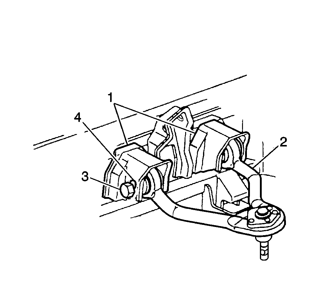
- Remove the following parts
from the upper control arm bracket (2):

- Lift the upper control
arm (2) up and to the side in order to gain access to the inner portion of
the frame bracket.
- Use the J 38794
in
order to remove the frame bracket knockout as follows:
| • | Do not distort the frame bracket when removing the knockout. |
| • | Apply extreme pressure lubricant to the threads of the T-bolt. |
| • | Insert the bolt through the knockout hole in the bracket support. |
| • | Install the bridge onto the T-bolt. |
| • | The forward bracket requires the bridge to be installed between the
legs of the bracket due to access problems. |
| | Notice: Do not subject the tool to more than 100 N·m (75 lb ft)
torque. Exceeding the recommended torque may damage the tool and/or the bracket.
|
| • | Assemble the following parts in order: |
| 2. | The bearing with the chamfered side out |
| • | The T-bolt head and the bridge must line up horizontally with
the knockout. |
| • | The bridge should span the knockout without interfering with the knockout
procedure. |
| • | Tighten the T-bolt head against the knockout by turning the nut
at the opposite end using a socket and torque wrench. |
| • | An open end wrench or adjustable wrench may be needed in order
to prevent the T-bolt from losing the horizontal alignment with the knockout. |
| • | If the torque limit on the T-bolt is met and the knockout does
not break free, use a die grinder of appropriate size. |
| • | Using the stamped outline as a guide, remove the knockout. |
| • | Remove the wax coating in the knockout area in order to make the perforation
lines more visible. |
| • | If the outline is not visible, use the T-bolt head installed horizontally,
as a template, and scribe the frame bracket. |
| • | Repeat the procedure on the other upper control arm frame bracket. |
Installation Procedure

- Install the upper control
arm (2) into the frame brackets.
- Install the bolts and the cams (4) through the frame brackets
and through the control arm (2).
- Install the cams (4) and the nuts.
Install the cams with the radius toward the frame brackets.
- Partially tighten the nut.
- Install the tire and the front wheel assemblies.
- Install the alignment machine heads.
Notice: Use the correct fastener in the correct location. Replacement fasteners
must be the correct part number for that application. Fasteners requiring
replacement or fasteners requiring the use of thread locking compound or sealant
are identified in the service procedure. Do not use paints, lubricants, or
corrosion inhibitors on fasteners or fastener joint surfaces unless specified.
These coatings affect fastener torque and joint clamping force and may damage
the fastener. Use the correct tightening sequence and specifications when
installing fasteners in order to avoid damage to parts and systems.
Important: Verify alignment specifications before proceeding. Refer to
Wheel Alignment Specifications
in Wheel Alignment.
- Adjust the caster and the camber to the correct specifications by rotating
the bolt head installed through the adjuster cam.
Tighten
- Tighten the front upper control arm nuts to 190 N·m
(140 lb ft).
- Tighten the rear upper control arm nuts to 190 N·m
(140 lb ft).
- Set the steering wheel on center with the wheels straight.
- Loosen the adjuster sleeve nuts.
- Adjust the toe-in. Refer to
Fastener Tightening Specifications
.
Tighten
Tighten the tie rod adjuster sleeve nuts to 19 N·m (14 lb ft).
- Ensure that the clamps are properly positioned. Refer to
Tie Rod Adjuster Replacement
in Steering Linkage.
- Recheck the alignment specifications.
- Lower the vehicle.


