Disassembly Procedure

- To remove the thrust support
assembly; refer to
Steering Gear Worm Gear Adjuster Seal and Stub Shaft Bearing Replacement
.
- Remove the stub shaft (1).
- Remove the valve assembly (2).
- Remove the stub shaft (1) from the valve assembly (2).
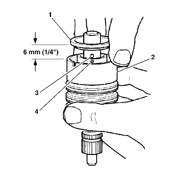
- Tap the stub shaft (1) lightly on a wood block in order
to loosen the shaft cap.
- Pull the shaft cap and the valve spool out from valve body (2)
6 mm (¼ inch).
- Disengage the stub shaft pin (3) from the hole in the valve
spool (4).

- If the valve assembly
needs repair, disassemble
the valve as follows:
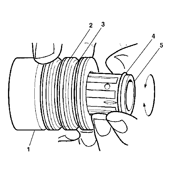
| 8.1. | Simultaneously pull and rotate the valve spool (5) in order
to remove the valve spool (5) from the valve body (1). |
| 8.2. | Remove the valve spool O-ring seal (4). |
| 8.3. | Alternately remove the valve body teflon rings (2) and
the O-ring seals (3). |
Assembly Procedure

- If the valve assembly
has been disassembled,
reassemble the valve as follows:
| 1.1. | Install the valve spool O-ring seal (4) to the valve spool (5). |
| 1.2. | Lubricate the valve spool (5) and O-ring seal (4)
with power steering fluid. |
| 1.3. | Simultaneously push and rotate the valve spool (5) into
the valve body (1) until the hole in the valve spool for the stub shaft
pin is accessible from the opposite end of the valve body (1). |

- Install the stub shaft
to the valve spool
as follows:
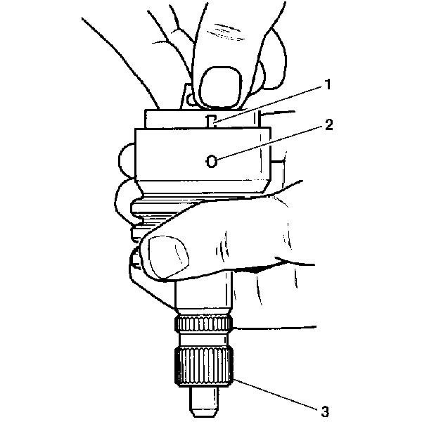
| 2.1. | Insert the stub shaft (3) into the valve spool. |
| 2.2. | Insert the pin. The notch in the stub shaft cap (1) must
fully engage the valve body pin (2). |
| 2.3. | Seat the stub shaft cap against the valve body shoulder. |
| 2.4. | Alternately install the O-ring seals and the teflon rings to the
valve body. |
| 2.5. | Lubricate the O-ring seals and the teflon rings with power steering
fluid. |

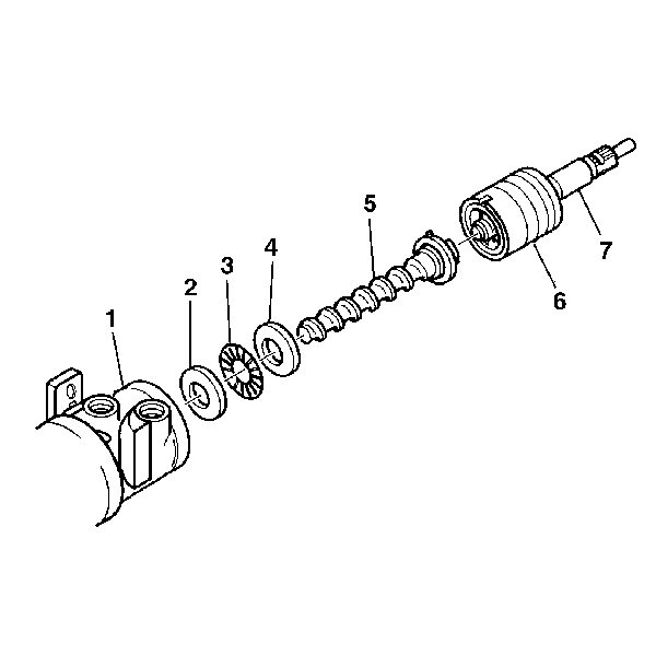
- Install the stub shaft (7)
and valve assembly (6) to the worm shaft (5). Ensure the pin
fits in the worm shaft to the slot in the valve assembly.
- To adjust the thrust support assembly; refer to
Steering Gear Worm Gear Adjuster Seal and Stub Shaft Bearing Replacement
.
- To adjust the pitman shaft over-center sector; refer to
Steering Gear Pitman Shaft Over-Center Preload Adjustment - Off Vehicle
.


