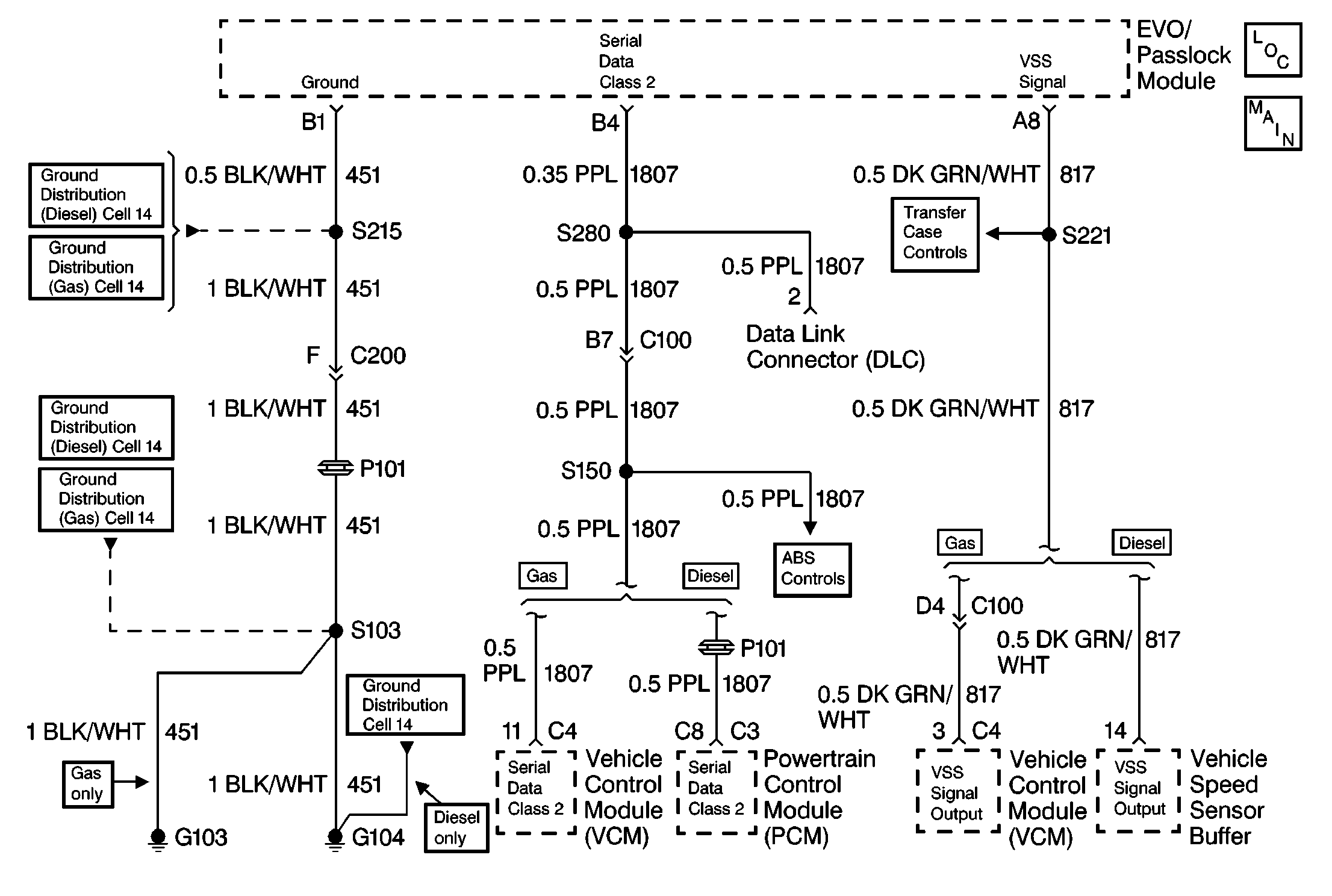
Circuit Description
The vehicle control module (VCM) in vehicles with gasoline engines or the powertrain control module (PCM) in vehicles with diesel engines and the class 2 data line provide the vehicle speed information to the electronic variable orifice (EVO)/Passlock™ module. Once the vehicle speed is detected, the EVO/Passlock™ module compares the vehicle speed signal received from the VSS with the vehicle speed data received from the class 2 data line. The VSS is a permanent magnet sensor producing an AC signal with varying frequency. The VSS is mounted in the transmission, or the transfer case in selectable four-wheel drive models. The VSS is driven off the output shaft. The VSS produces a pulsing AC voltage when the vehicle speed is greater than 5 km/h (3 mph). The AC voltage and the number of pulses increase with the vehicle speed. The VCM/PCM supplies the vehicle speed signal to the instrument cluster and to the EVO/Passlock™ module.
Conditions for Setting the DTC
- The vehicle speed sensor message is less than 5 km/h (3 mph). Simultaneously, for 10 seconds, the class 2 vehicle speed message is 10 km/h (6 mph) greater than the VSS message.
- Five consecutive class 2 samples met the above conditions.
Action Taken When The DTC Sets
The EVO/Passlock™ module will not send any current to the power steering solenoid actuator. This will cause the retraction of the power steering solenoid actuator valve, providing maximum fluid flow and full power steering assist at all times.
Conditions For Clearing The DTC
| • | A history DTC will clear after 100 consecutive ignition cycles have occurred without a fault. |
| • | The history and the current DTC can be cleared by using the scan tool. |
Diagnostic Aids
| • | Check for the powertrain DTC P0500 or any other vehicle speed related codes. If those codes are present, perform those diagnostic tables first. |
| • | The scan tool shows vehicle speed when the drive wheels are turning faster than 5 km/h (3 mph). Do not use the vehicle speed display if the drive wheels are not turning. |
| • | A poor connection, a break in the wire insulation exposing the internal wire, or wire that is broken inside the insulation can cause an intermittent problem. |
| • | Thoroughly check the EVO/Passlock™ module, the VCM, and PCM for the following conditions: |
| - | Terminals that have backed out |
| - | Broken locks |
| - | An improperly formed or damaged terminal |
| - | Weak terminal retaining tension |
| - | Proper routing |
Test Description
The numbers below refer to the step numbers on the diagnostic table.
-
This step ensures that the Variable Effort Steering System Check has been performed.
-
This step checks the vehicle speed signal to the vehicle control module (VCM) (gasoline engines) or to the powertrain control module (PCM) (diesel engines).
-
This step makes sure the other systems on the same circuit are receiving a vehicle speed sensor (VSS) signal.
Step | Action | Value(s) | Yes | No |
|---|---|---|---|---|
1 | Was the Variable Effort Steering System Check performed? | -- | Go to Step 2 | |
2 | Does the speedometer operate correctly? | -- | Go to Step 3 | Go to Step 4 |
3 |
Are any stored (PCM) or (VCM) VSS codes set? | -- | Go to Step 4 | Go to Step 5 |
4 |
Are any DTCs stored? | -- | Go to the applicable DTC table | |
5 | Inspect for an open in the DK GRN/WHT (817) wire. Refer to General Electrical Diagnosis in Wiring Systems. Did you find and correct a problem? | -- | Go to Step 7 | Go to Step 6 |
6 | Replace the electronic variable orifice (EVO)/Passlock™ module. Refer to Theft Deterrent Module Replacement in Theft Deterrent. Are any DTCs stored? | -- | Go to the applicable DTC table | |
7 |
Is DTC C0000 current? | -- | System OK |
