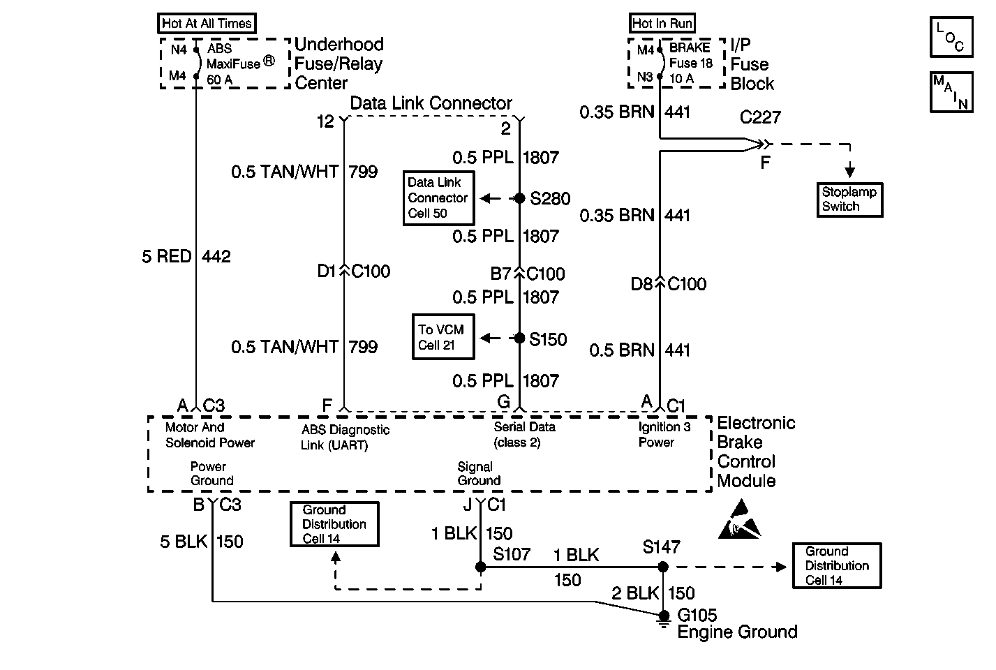
System Description
The diagnostic system check is an organized approach to identifying an Antilock Brake System (ABS) malfunction. The diagnostic system check must be the starting point for any ABS complaint diagnosis. The diagnostic system check directs the service technician to the next logical step in diagnosing the complaint. Refer to the table below.
Diagnostic serial data is transmitted/received by the EBCM through connector C1, terminal F (over 15,000 GVW), or terminal G (under 15,000 GVW). The EBCM is supplied switched ignition voltage through connector C1, terminal A, and ground is provided through connector C1, terminal J.
Diagnostic Aids
Excessive resistance in the ground or power supply circuits will not allow communication with the EBCM. If communication with the EBCM is not possible, ensure that the ABS ground connection is good and that there is no excessive resistance in any of the power supply circuits.
Test Description
The numbers below refer to the steps in the diagnostic table:
-
This step checks for normal ABS indicator lamp operation.
-
This step checks for ignition voltage at the EBCM.
-
This step checks for high resistance in the ground circuit.
-
This step checks for high resistance in the ignition voltage circuit.
-
This step checks for a short to ground in the ignition voltage circuit.
-
This step decides between ABS indicator lamp on always, or off always as the symptom.
-
This step decides between a short to ground in the 10-way EBCM harness/connector, or an internal EBCM fault.
Step | Action | Value(s) | Yes | No |
|---|---|---|---|---|
1 |
Is data being received from the EBCM? | -- | Go to Step 2 | Go to Step 4 |
2 | Using the Scan Tool , check for any DTCs. Are any current or history DTCs displayed? | -- | Go to DTC LIST | Go to Step 3 |
Did the ABS indicator lamp turn on for two seconds and then turn off? | -- | System is operating normally. Go to Diagnostic Aids. | Go to Step 11 | |
Is the voltage measured within the specified range? | 10-15V | Go to Step 5 | Go to Step 9 | |
Is the resistance measured within the specified range? | 0-2ohms | Go to Step 6 | Go to Step 12 | |
6 |
Is the terminal contact or the connection poor? | -- | Go to Step 7 | Go to Step 8 |
7 | Replace the terminals or repair the poor connection. Refer to Repairing Connector Terminals . Is the repair complete? | -- | Go to Step 1 | -- |
8 | Reconnect the EBCM connectors and the battery cables. Are the EBCM connectors and the battery cables reconnected? | -- | Go to Diagnostic System Check - Data Link Communications in Wiring Systems | -- |
Is the resistance measured within the specified range. | 0-2ohms | Go to Step 10 | Go to Step 13 | |
Is the resistance measurement equal to the specified value? | OL | Go to Step 15 | Go to Step 14 | |
Observe the ABS indicator lamp. Does the ABS indicator lamp stay on? | -- | Go to ABS Indicator Always On | ||
12 | Repair open or high resistance in CKT 150. Is the repair complete? | -- | Go to Step 1 | -- |
13 |
Is the repair complete? | -- | Go to Step 1 | -- |
14 |
Is the repair complete? | -- | Go to Step 1 | -- |
Inspect CKT 441 and the 10-way EBCM harness connector for physical damage which may result in a short to ground with the 10-way EBCM harness connector connected to the EBCM. Is there evidence of damage? | -- | Go to Step 16 | Go to Step 17 | |
16 | Repair the terminals which are damaged. Refer to Repairing Connector Terminals . Is the repair complete? | -- | Go to Step 1 | -- |
17 |
Is the repair complete? | -- | Go to Step 1 | -- |
