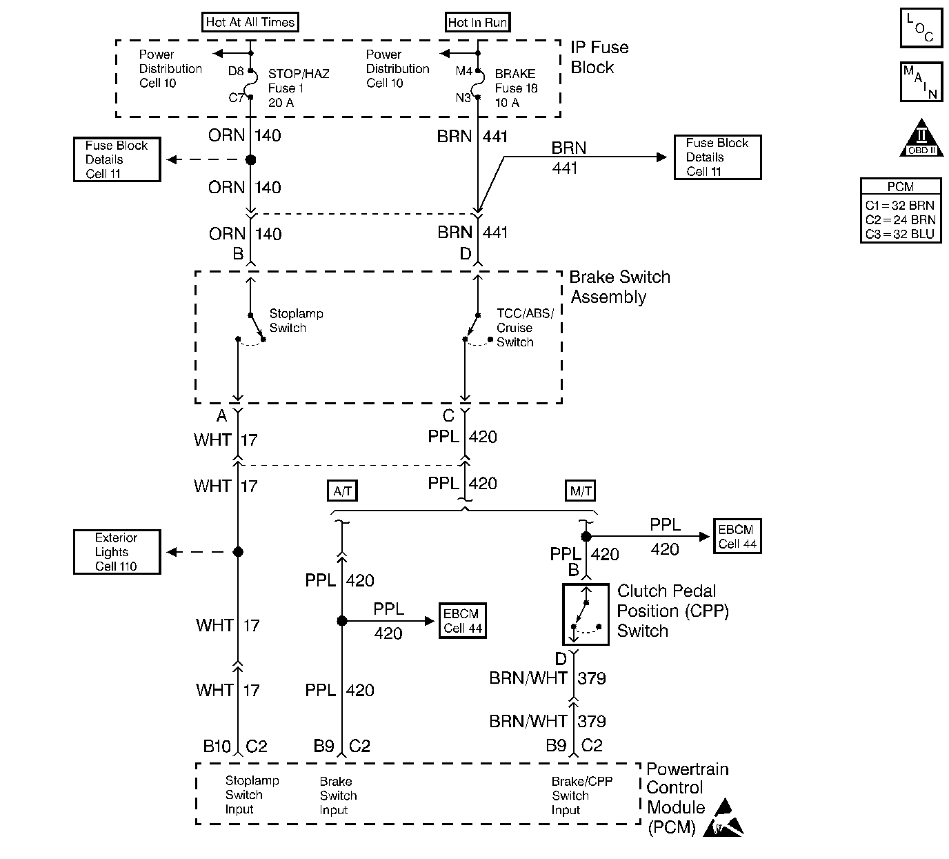
Circuit Description
The TCC normally closed cruise brake switch supplies a B+ signal on the Brake Switch Input circuit to the PCM. The circuit is opened when the brakes are applied. The stop lamp/cruise control normally open brake switch supplies a B+ signal on the Stoplamp Switch Input circuit to the PCM when the brake is applied.
Conditions for Running the DTC
| • | Brake switches disagree for 10 consecutive minutes. |
| or |
| • | TCC and cruise control brake switches are not toggling open and closed, during 6 brake applications on the same ignition cycle. |
Conditions for Setting the DTC
| • | Brake switches disagree for 10 consecutive minutes. |
| or |
| • | TCC and cruise control brake switches are not toggling open and closed, during 6 brake applications on the same ignition cycle. |
Action Taken When the DTC Sets
| • | The PCM disallows all cruise control inputs. |
| • | TCC shift schedules may be affected. |
| • | The PCM will not illuminate the Malfunction Indicator Lamp (MIL). |
| • | The PCM records the operating conditions at the time the diagnostic fails. This information stores in the Failure Records. |
Conditions for Clearing the MIL/DTC
| • | A History DTC clears after forty consecutive warm-up cycles, if this or any other emission related diagnostic does not report any failures |
| • | The use of a scan tool. |
Diagnostic Aids
Refer to PCM Intermittent Diagnostic Trouble Codes or Performance. Check customer driving habits and/or unusual traffic conditions (i.e. stop and go, expressway traffic).
Test Description
Number(s) below refer to the step number(s) on the Diagnostic Table.
Step | Action | Value(s) | Yes | No |
|---|---|---|---|---|
1 |
Important: Before clearing any DTCs, use the scan tool Capture Info to save freeze frame and failure records for reference, as the scan tool loses data when using the Clear Info function. Was the Powertrain On-Board Diagnostic (OBD) System Check performed? | -- | ||
2 |
Does the scan tool display the cruise brake switch Closed and then Open when the brake is applied? | -- | ||
3 | Apply the brakes again. Does the scan tool display the brake switch Open and then Closed when the brake is applied? | -- | ||
Is the test light ON? | -- | |||
5 |
Is the test light ON? | -- | ||
Does the scan tool display the brake switch Closed? | -- | |||
7 |
Is the test light ON? | -- | ||
8 |
Does the scan tool display the Cruise Brake switch Closed? | -- | ||
9 | The DTC is intermittent. If no additional DTCs are stored, refer to Diagnostic Aids. If additional DTCs were stored refer to the applicable DTC table(s) first. Are any additional DTCs stored? | -- | Go to the Applicable DTC Table | Go to Diagnostic Aids |
10 | Check the normally open feed circuit (terminal B) for and open or short to ground. Is the action complete? | -- | -- | |
11 |
Is the action complete? | -- | ||
12 | Check the normally open brake switch signal circuit for and open or short to ground. Was a repair performed? | -- | ||
13 | Check the normally open brake switch signal circuit for a proper connection at PCM? Was a repair performed? | -- | ||
14 | Check the normally closed feed circuit (terminal F) for and open or short to ground. Is the action complete? | -- | -- | |
15 | Check the normally closed cruise brake switch signal circuit for an open or short to ground. Was a repair performed? | -- | ||
16 | Check the normally closed cruise brake switch signal circuit for a proper connection at PCM? Was a repair performed? | -- | ||
17 | Replace the stoplamp switch. Is the action complete? | -- | -- | |
18 |
Important: The new PCM must be programmed. Refer to Powertrain Control Module Replacement/Programming . Replace the PCM. Is the action complete? | -- | -- | |
19 |
Does the Scan Tool indicate the diagnostic Passed? | -- | ||
20 | Does the Scan tool display any additional undiagnosed DTCs? | -- | Go to the Applicable DTC Table | System OK |
