For 1990-2009 cars only
Ignition and Key Alarm Switch Assembly - Assemble - Off Vehicle Floor Shift
Tools Required
J-42759 Ignition Switch Connector Release Tool
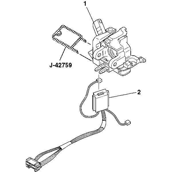
- Insert J-42759 into the electronic lock module assembly (1) and slide the ignition and key alarm switch assembly (2) in.
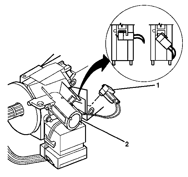
- Install the key alarm connector (1) into the electronic lock module assembly (2).
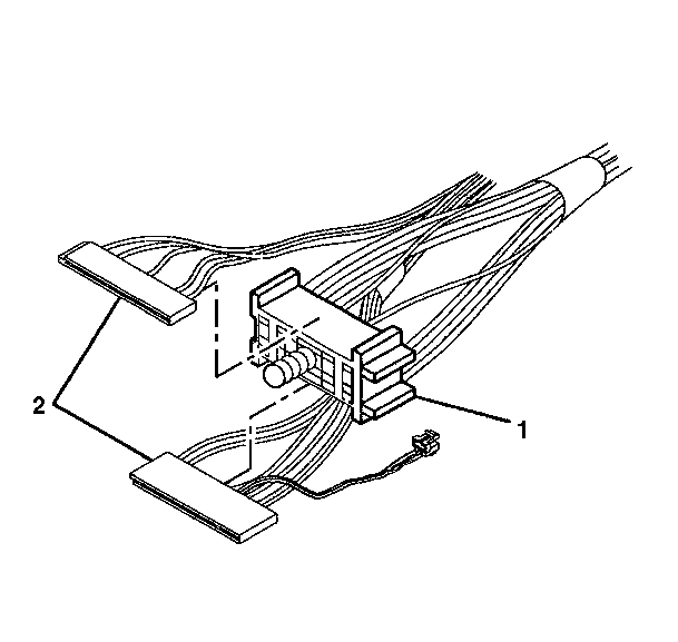
- Slide the 2 connectors (2) of the turn signal and multifunction switch assembly into the bulkhead connector (1).
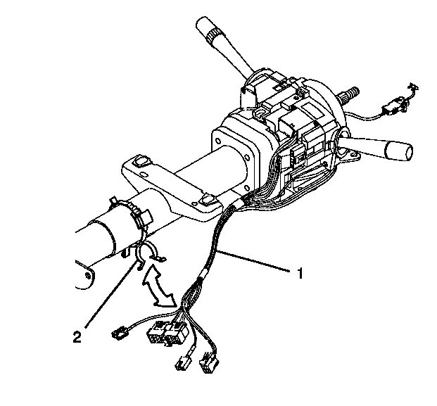
- Attach the wire harness assembly (1) to the steering column with new wire harness strap (2).
- Install the upper and lower trim covers. Refer to Steering Column Trim Covers - Assemble - Off Vehicle .
- Enable the inflatable restraint steering wheel module. Refer to Enabling the SIR System .


| 2.1. | Push the key alarm connector (1) into the electronic lock module assembly (2). |
| 2.2. | Rotate the key alarm connector (1) 90 degrees so that the key alarm connector (1) locks into place. |
| 2.3. | Install the passkey connector into the electronic lock module assembly (2). |


Important: The abrasion sleeve must be installed back onto the steering column wire harness assembly. The electronic lock module assembly wires and connector must be hanging out of the middle of the abrasion sleeve.
Ignition and Key Alarm Switch Assembly - Assemble - Off Vehicle Column Shift
Tools Required
J-42759 Ignition Switch Connector Release Tool
- Insert J-42759 into the electronic lock module assembly (1) and slide the ignition and key alarm switch assembly (2) in.
- Push the key alarm connector (1) into the electronic lock module assembly (2).
- Rotate the key alarm connector (1) 90 degrees so that the key alarm connector (1) locks into place.
- Install the passkey connector into the electronic lock module assembly (2).
- Slide the 2 connectors (2) of the turn signal and multifunction switch assembly into the bulkhead connector (1).
- Attach the wire harness strap (2) to the wire harness assembly (1) and the steering column.
- Install the upper and lower trim covers. Refer to Steering Column Trim Covers - Assemble - Off Vehicle .
- Enable the inflatable restraint steering wheel module. Refer to Enabling the SIR System .


Important: The abrasion sleeve must be installed back onto the steering column wire harness assembly. The electronic lock module assembly wires and connector must be hanging out of the middle of the abrasion sleeve.
