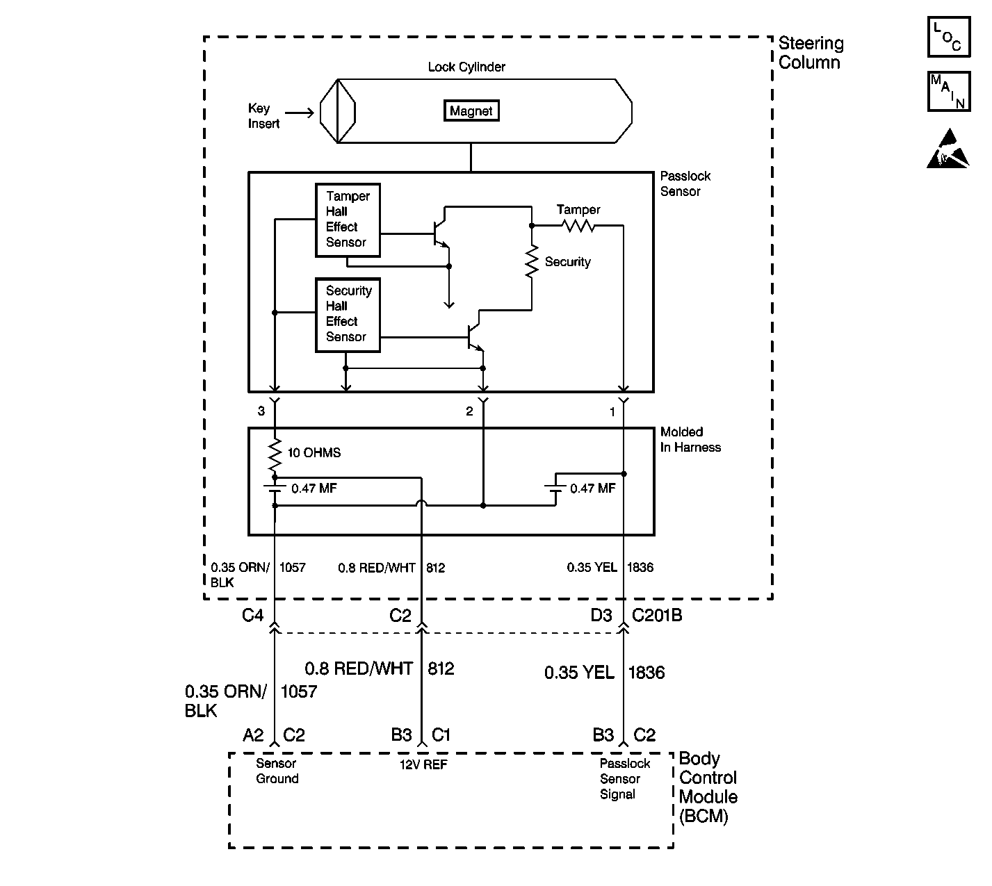
Circuit Description
The body control module (BCM) supplies power to the Passlock sensor on CKT 812.
When the Passlock sensor is powered and the ignition switch is rotated to the CRANK position, the hall effect security sensor will latch and provide a code to the BCM. The BCM will then compare this code to the code in the previous ignition cycle. If the latched value is the same as the last ignition cycle value, the test has passed. When the ignition switch is switched to the OFF position, the sensor is no longer powered and resets the sensor latch circuit.
In the next ignition cycle, the Passlock sensor waits for an ignition switch crank input and verifies the sensor code and compares the sensor code to the last stored valid code.
Conditions for Setting the DTC
| • | The ignition switch is in the ON position. |
| • | The BCM is unable to produce the 9-16 volts required for the Passlock sensor operation. This may be due to a module, a wiring, or a sensor problem. |
Action Taken When the DTC Sets
| • | The vehicle does not start if the fault occurs before you start the vehicle. The security telltale will be ON. |
| • | If the vehicle is running when the fault occurs, the BCM will be in the fail enable mode allowing the vehicle to start and to run. The security indicator will be ON. |
Conditions for Clearing the MIL/DTC
| • | The DTC will clears after an ignition cycle occurs without the fault recurring. |
| • | The BCM history codes clears after 100 concurrent ignition cycles occur without the fault recurring. |
| • | Using a scan tool. |
Diagnostic Aids
| • | When replacing the Passlock sensor, all of the following components are included as a replacement part and must be replaced: |
| - | The lock |
| - | The sensor |
| - | The filter |
| - | The harness |
| • | Use a scan tool in order to inspect the Passlock data voltage and the Passlock code. |
| • | Perform a visual inspection of the wiring and the connectors. |
| • | Inspect the Passlock sensor harness for an intermittent or a short to battery. Refer to Intermittents and Poor Connections Diagnosis in Wiring Systems. |
Test Description
The numbers below refer to the step number(s) on the diagnostic table.
-
This test inspect for a short to ground of CKT 812.
-
This step inspects for a short between CKT 812 and CKT 1057.
-
This step isolates the short in CKT 812 between the harness and the Passlock sensor.
-
This step isolates the short in CKT 812 and CKT 1057 between the harness and the Passlock sensor.
Step | Action | Value(s) | Yes | No |
|---|---|---|---|---|
1 | Did you perform the Vehicle Theft Deterrent (VTD) System Check? | -- | Go to Step 2 | |
Does the meter indicate the specified value? | Less than 5ohms | Go to Step 5 | Go to Step 3 | |
Use a J 39200 DMM in order to measure the resistance from the connector C1 terminal B3 to connector C2 terminal A2. Does the meter indicate the specified value? | Less than 1000ohms | Go to Step 8 | Go to Step 4 | |
4 | Replace the BCM. Refer to Body Control Module Replacement in Body Control Systems. Is the repair complete? | -- | Go to Step 10 | -- |
Does the meter indicate the specified value? | Less than 5ohms | Go to Step 7 | Go to Step 6 | |
6 |
Is the repair complete? | -- | Go to Step 10 | -- |
7 | Locate and repair the short to ground in CKT 812. Is the repair complete? | -- | Go to Step 10 | -- |
Does the J 39200 DMM indicate the specified value? | Less than 1000ohms | Go to Step 9 | Go to Step 6 | |
9 | Locate and repair the short between CKT 812 and ground. Is the repair complete? | -- | Go to Step 10 | -- |
10 |
Is the operation complete? | -- | -- |
