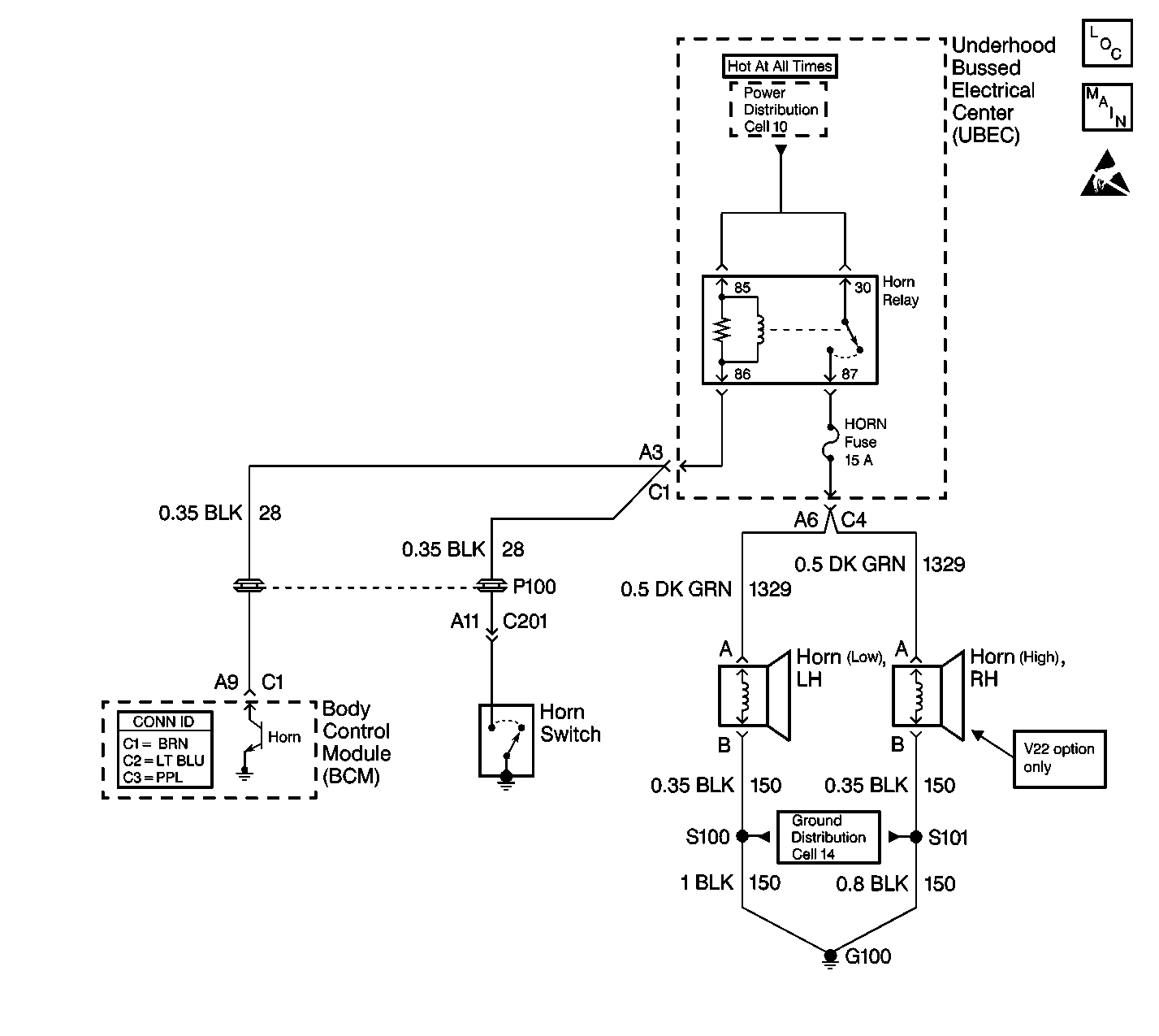
Circuit Description
CKT 28 is an input to the body control module (BCM). The BCM monitors CKT 28 in order to determine if the horn circuit is open or shorted to ground.
Conditions for Setting the DTC
| • | When CKT 28 is open or shorted to ground for approximately 3 minutes the BCM will set B2752. |
| • | The system voltage must be between 9.0-16.0 volts. |
Action Taken When the DTC Sets
| • | If CKT 28 is shorted to ground the horns will remain ON at all times. |
| • | If CKT 28 is open the horn will only work with the horn button on the steering wheel. |
Conditions for Clearing the MIL/DTC
| • | A current DTC will clear immediately after the condition for setting the fault is corrected. |
| • | A history DTC will clear after 100 consecutive ignition cycles without a fault present. |
| • | Use a scan tool in order to clear history and current DTCs. |
Diagnostic Aids
| • | If the customers complaint is that the horns are always on, remove the HORN fuse located in the underhood bussed electrical center (UBEC) so the system can be diagnosed without the horns on. |
| • | Always diagnose the first DTC listed on the scan tool. |
| • | The scan tool must display DTC B2752 as a current code before performing diagnostics. |
| • | Inspect for a sticking horn pad and or switch. |
| • | Perform a visual inspection for loose or poor connections at all related components. |
| • | Refer to Clearing DTCs in Wiring Systems for intermittent and poor connections. |
Test Description
Step number(s) below refer to the same step number(s) in the Diagnostic Table
Step | Action | Value(s) | Yes | No |
|---|---|---|---|---|
1 | Was the BCM Diagnostic System Check performed? | -- | ||
2 |
Are the horns on at all times? | -- | ||
3 |
Does the test lamp light? | -- | ||
4 | Push the horn button on the steering wheel. Does the horn sound with the horn button? | -- | ||
5 |
Does the DMM display battery voltage? | -- | ||
6 |
Does the DMM display battery voltage? | -- | ||
7 | With a DMM, measure the resistance between terminals 85 and 86 of the horn relay. Is the resistance at or above the specified value? | 65ohms | ||
8 | Locate and repair the short to ground in CKT 28 (BLK). Is the repair complete? | -- | -- | |
9 | Locate and repair the open in CKT 28 (BLK) between the BCM and the horn relay. Is the repair complete? | -- | -- | |
10 | Replace the Underhood Bussed Electrical Center (UBEC). Is the repair complete? | -- | -- | |
11 | Replace the horn relay. Is the repair complete? | -- | -- | |
12 |
Is the repair complete? | -- | System OK | -- |
13 | Clear the DTCs. Refer to Clearing DTCs . Is the action complete? | -- | System OK | -- |
