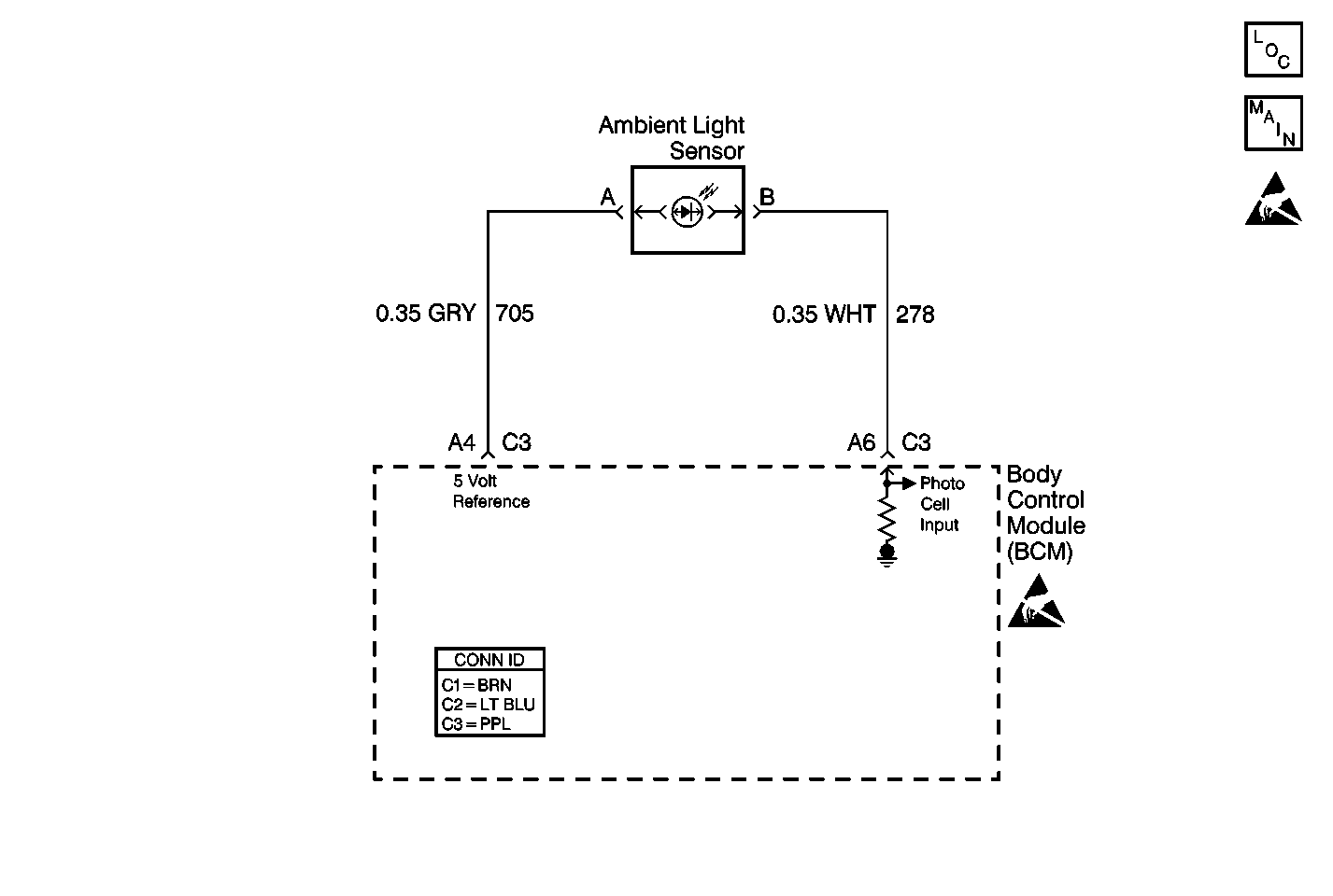
Circuit Description
The body control module (BCM) monitors CKT 278 in order to determine if the daytime running lights (DRL) or the auto headlights (AHL) should be turned ON in the AUTO mode. When the BCM senses the ambient light sensor voltage between 1.7-4.7 volts (light state) the DRL will be commanded ON. When the BCM senses the ambient light sensor voltage between 0.2-1.0 volts (park state) the AHL will be commanded .
Conditions for Setting the DTC
| • | When the ambient light sensor input voltage is less than 0.2 volts (CKT 278 is open or shorted to ground). |
| • | The system voltage must be between 9.0-16.0 volts. |
| • | The above conditions must be met for 0.5 seconds |
Action Taken When the DTC Sets
The AHL will remain ON in any ambient light state.
Conditions for Clearing the MIL/DTC
| • | This DTC will clear immediately after the condition for setting the fault is corrected. |
| • | A history DTC will clear after 100 consecutive ignition cycles without a fault present. |
| • | Use a scan too in order to clear history and current DTCs. |
Diagnostic Aids
| • | Always perform the first DTC listed on the scan tool if more than 1 DTC is displayed. |
| • | The scan tool must display DTC B2647 as a current code before performing diagnostics. |
| • | Perform a visual inspection for loose or poor connections at all related components. |
| • | Refer to Intermittents and Poor Connections Wiring Systems. |
Test Description
Step number(s) below refer to the same step number(s) in the Diagnostic Table.
-
This step tests the ambient light sensor CKT 278 for an open.
-
This step tests the ambient light sensor CKT 278 for a short to ground.
Step | Action | Value(s) | Yes | No |
|---|---|---|---|---|
1 | Was the BCM Diagnostic System Check performed? | -- | ||
2 |
Is the voltage within the specified values? | 1.1-4.7 volts | ||
3 |
Is the resistance within the specified range? | 0-5ohms | ||
4 | Connect a test lamp to B+ and probe the ambient light sensor CKT 278 (WHT) cavity B. Does the test lamp light? | -- | ||
5 | With a J 39200 DMM, measure the resistance between the ambient light sensor CKT 705 (GRY) cavity A and the purple BCM (C3) connector cavity A4 . Is the resistance within the specified range? | 0-5ohms | ||
6 | Locate and repair the open GRY (705) wire between the ambient light sensor and the BCM. Is the repair complete? | -- | -- | |
7 | Locate and repair the open in CKT 278 (WHT) between the ambient light sensor and the BCM. Is the repair complete? | -- | -- | |
8 | Locate and repair short to ground on CKT 278 (WHT) between the ambient light sensor and the BCM? Is the repair complete? | -- | -- | |
9 | Replace the ambient light sensor. Is the repair complete? | -- | -- | |
10 |
Is the repair complete? | -- | System OK | -- |
11 | Clear the DTCs. Refer to Clearing DTCs . Is the action complete? | -- | System OK | -- |
