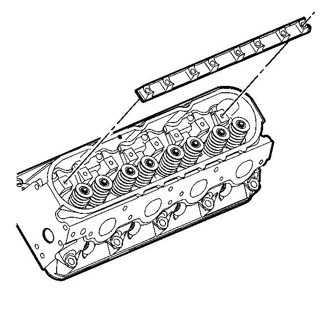
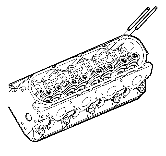
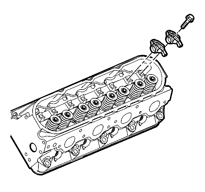
- Lubricate the valve rocker arms and pushrods with clean engine oil.
- Lubricate the flange of the valve rocker arm bolts with clean engine oil.
- Install the valve rocker arm pivot support.
- Install the pushrods.
- Install the rocker arms and bolts.
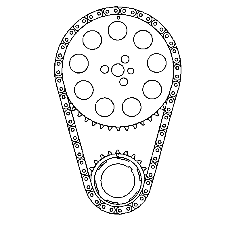
- Rotate the crankshaft until number one piston is at top dead center of compression stroke.
- With the engine in the number one firing position, tighten the following valve rocker arm bolts:
- Rotate the crankshaft 360 degrees.
- Tighten the following valve rocker arm bolts:

Important:
• When using the valve train components again, always install the components
to the original location and position. • Valve lash is net build, no valve adjustment is required.
Lubricate the flange or washer surface of the bolt that will contact the valve rocker arm.

Important: Ensure that the pushrods seat properly to the valve lifter sockets.

Important:
• Ensure that the pushrods seat properly to the ends of the rocker arms. • DO NOT tighten the rocker arm bolts at this time.

In this position, cylinder number one rocker arms will be off lobe lift, and the crankshaft sprocket key will be at the 1:30 position. If viewing from the rear of the engine, the additional crankshaft pilot hole, non-threaded, will be in the 10:30 position.
The engine firing order is 1, 8, 7, 2, 6, 5, 4, 3.
Cylinders 1, 3, 5 and 7 are left bank.
Cylinders 2, 4, 6, and 8 are right bank.
Notice: Use the correct fastener in the correct location. Replacement fasteners must be the correct part number for that application. Fasteners requiring replacement or fasteners requiring the use of thread locking compound or sealant are identified in the service procedure. Do not use paints, lubricants, or corrosion inhibitors on fasteners or fastener joint surfaces unless specified. These coatings affect fastener torque and joint clamping force and may damage the fastener. Use the correct tightening sequence and specifications when installing fasteners in order to avoid damage to parts and systems.
Tighten
| • | Tighten exhaust valve rocker arm bolts 1, 2, 7, and 8 to 30 N·m (22 lb ft). |
| • | Tighten intake valve rocker arm bolts 1, 3, 4, and 5 to 30 N·m (22 lb ft). |
Tighten
| • | Tighten exhaust valve rocker arm bolts 3, 4, 5, and 6 to 30 N·m (22 lb ft). |
| • | Tighten intake valve rocker arm bolts 2, 6, 7, and 8 to 30 N·m (22 lb ft). |
