Tools Required
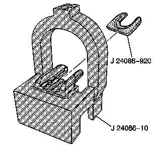
J 24086-C Piston Pin Remover/Installer Set
- Install fork insert J 24086-920 into J 24086-10 .
- Use a torch and apply MILD heat to the pin end of the connecting rod. Mild heating of the connecting rod will ease in piston and pin assembly.
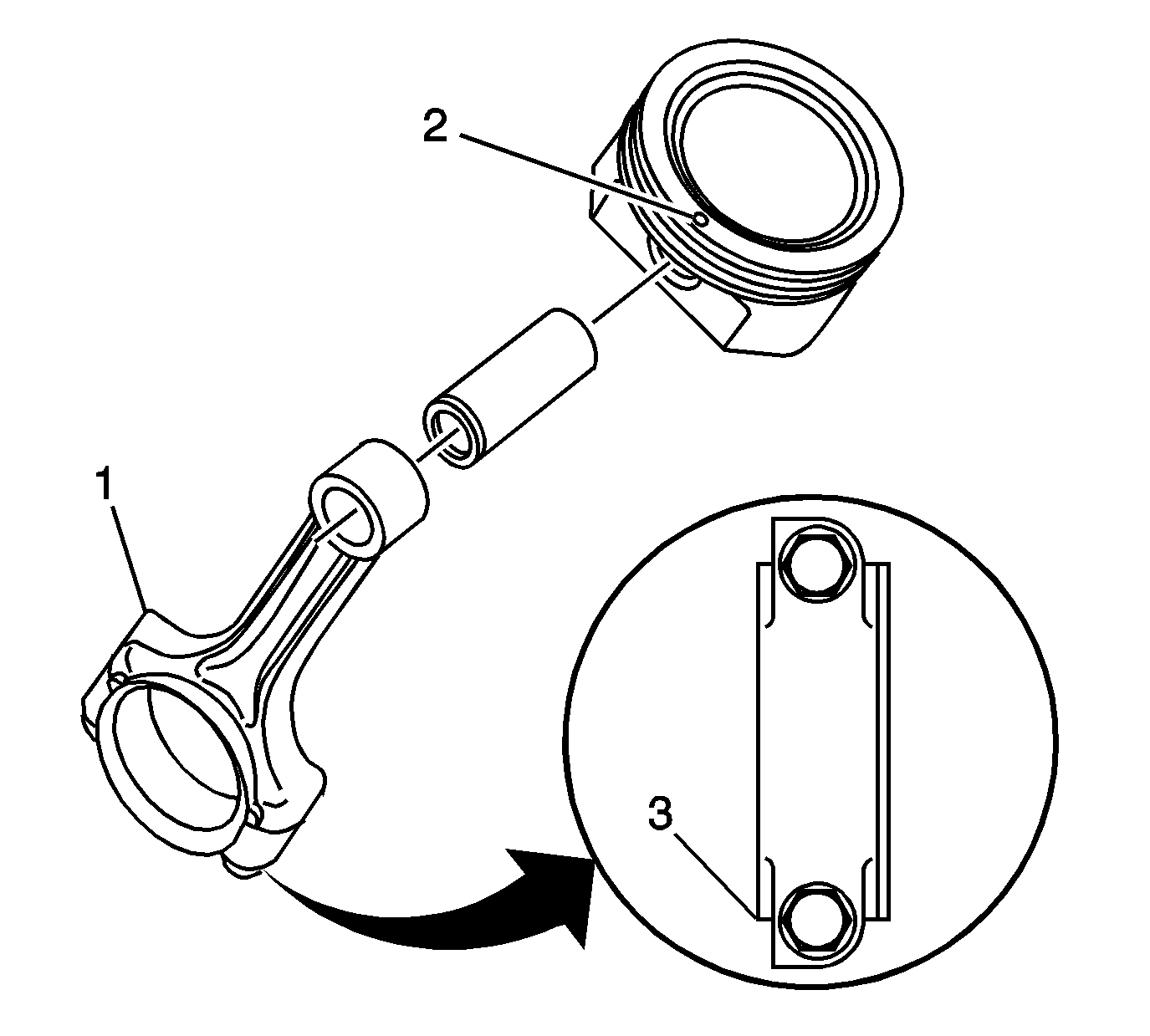
- Identify the positioning tab (1) or flat flange (3) of the connecting rod. When properly assembled, the positioning tab or flat flange of the rod and the mark (2) on the top of the piston should both be facing the front of the engine.
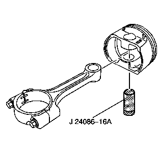
- Assemble the piston, the connecting rod, and the J 24086-16A.
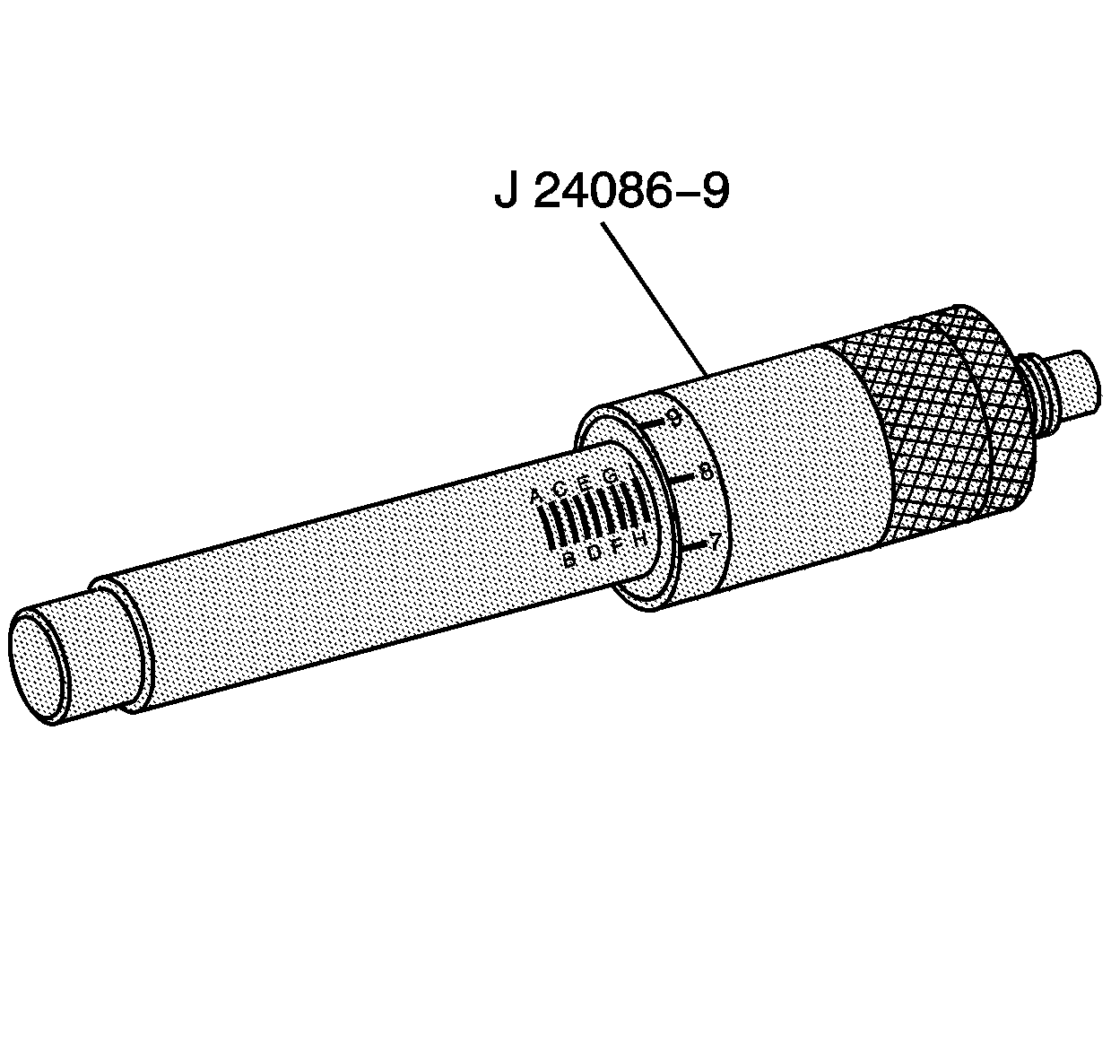
- Adjust the J 24086-9 to I 8.
- Install the piston, connecting rod, piston pin, and J 24086-16A to the J 24086-10 .
- Insert J 24086-9 through J 24086-10 and to the piston pin.
- Press J 24086-9 until the installer bottoms on the J 24086-10 .
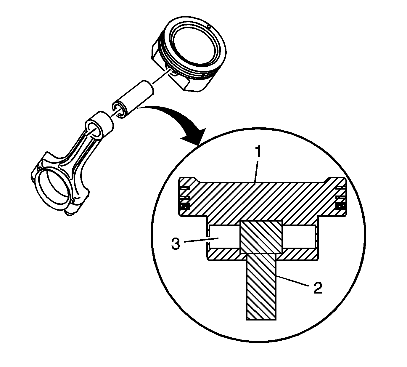
- Inspect the piston (1), pin (3), and connecting rod (2) for proper assembly.
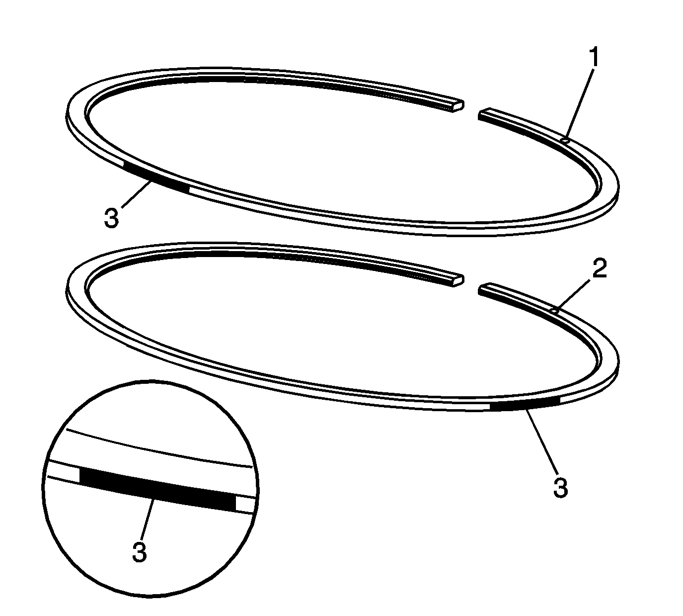
- Identify the compression and oil control rings for proper installation. The upper compression ring can be identified by a paint mark (3) located 180 degrees from the end gap. The lower compression ring can be identified by a paint mark (3) located 90 degrees from the end gap. Both rings should be installed with the orientation marks (1, 2) facing the top of the piston.
- Using piston ring pliers, install the piston rings onto the piston.
- Position the oil control ring end gaps a minimum of 25 mm (1.0 in) from each other.
- Position the compression ring end gaps 180 degrees opposite each other.
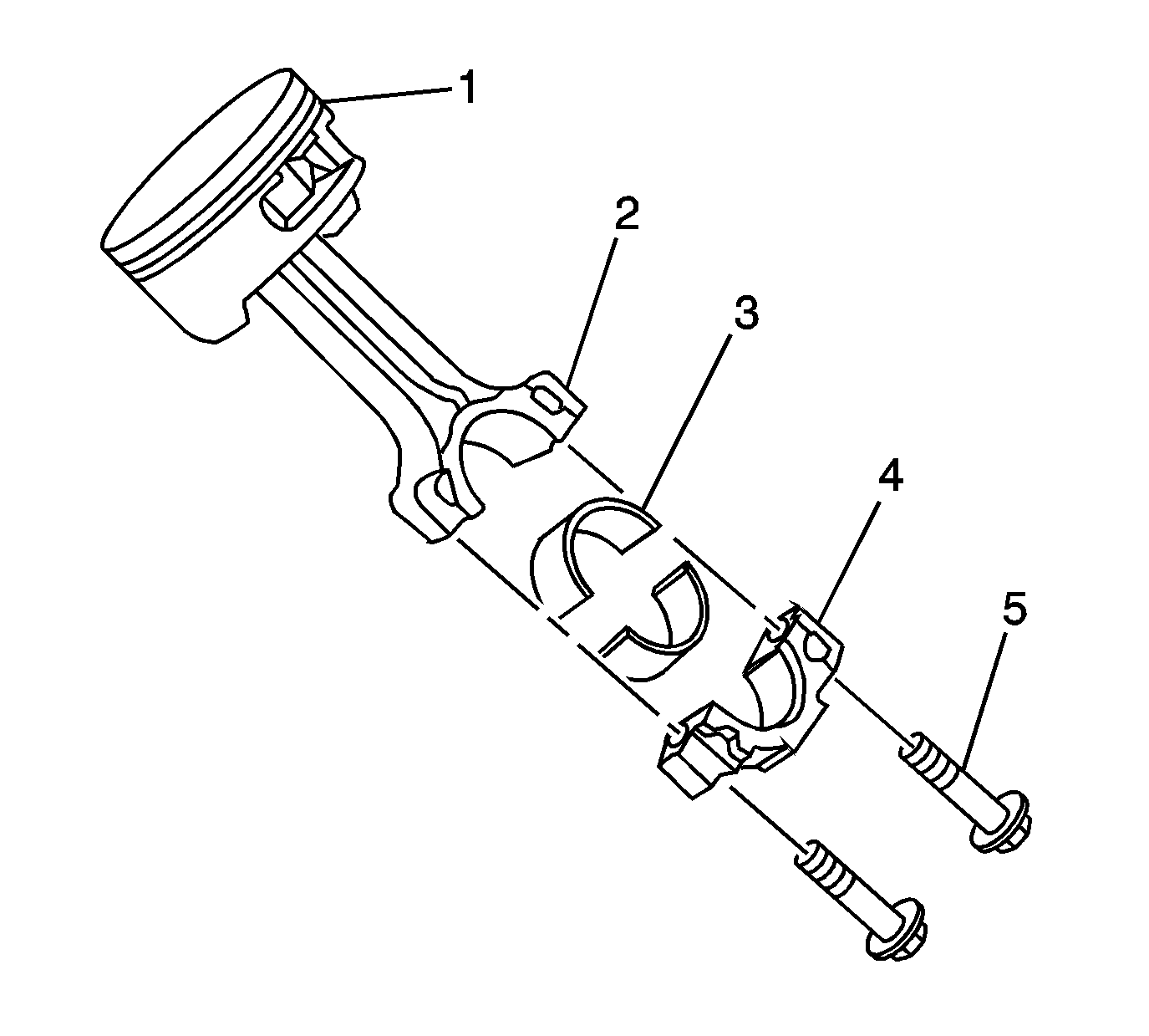
- Install the connecting rod bearings (3) to the rod (2) and cap (4).
Important:
• Disassembly of the piston, press-fit design piston pin, and connecting
rod may create scoring or damage to the piston pin and piston pin bore. If
the piston, pin, and connecting rod have been disassembled, replace the components
as an assembly. • If reusing the piston and connecting rod assembly, install the assembly
to the original cylinder and corresponding crankshaft journal. • The assembly procedure, as shown, is to be used for diagnostic purposes
only.
Caution: Avoid contact with HOT components. Wear safety glasses and protective gloves to avoid personal injury.
Notice: Applying excessive heat to the connecting rod may damage or distort the rod. Rod temperature SHOULD NOT exceed 315°C (600°F). At this temperature the end of the connecting rod will turn a straw color upon visual inspection.
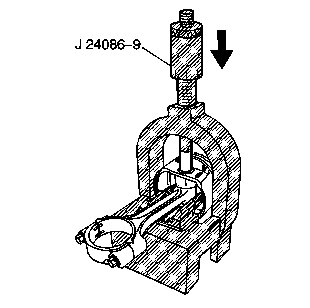
Notice: After the installer hub bottoms on the support assembly, do not exceed 35 000 kPa (5,000 psi) pressure, this could cause damage to the tool.
When properly installed, the piston pin (3) should be centered in the connecting rod (2).
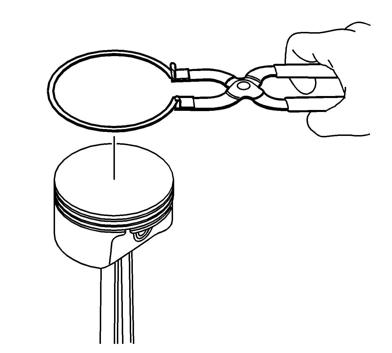
Important: When installing piston rings, use a ring expander plier type tool. Do not roll the rings into the grooves of the piston. Use caution and care to expand the rings only slightly larger than the outside diameter (OD) of the piston.
