Steering Gear Replacement Non-Rack and Pinion
Removal Procedure
- Raise the vehicle.
- Remove the shield. Refer to Shield Replacement in Front Drive Axle.
- Place a drain pan below the steering gear.
- Remove the hoses from the steering gear.
- Disconnect the intermediate shaft from the steering gear. Refer to Intermediate Steering Shaft Replacement in Steering Wheel and Column-Tilt.
- Disconnect the pitman arm from the relay rod. Refer to Pitman Arm Replacement in Steering Linkage.
- Remove the steering gear frame bolts and the steering gear.
| 4.1. | Raise the hose up in order to prevent oil drainage. |
| 4.2. | Cap or tape the ends of the hose and the gear fittings in order to prevent the entrance of dirt. |
Installation Procedure
- Place the steering gear in position.
- Install the steering gear to the frame bolts.
- Install the pitman arm. Refer to Pitman Arm Replacement in Steering Linkage.
- Install the intermediate shaft. Refer to Intermediate Steering Shaft Replacement in Steering Wheel and Column-Tilt.
- Remove the plugs and the caps from the steering gear and the hoses.
- Connect the hoses to the steering gear.
- Install the shield. Refer to Shield Replacement in Front Drive Axle.
- Bleed the system. Refer to Power Steering System Bleeding .
- Lower the vehicle.
Notice: Use the correct fastener in the correct location. Replacement fasteners must be the correct part number for that application. Fasteners requiring replacement or fasteners requiring the use of thread locking compound or sealant are identified in the service procedure. Do not use paints, lubricants, or corrosion inhibitors on fasteners or fastener joint surfaces unless specified. These coatings affect fastener torque and joint clamping force and may damage the fastener. Use the correct tightening sequence and specifications when installing fasteners in order to avoid damage to parts and systems.
Tighten
Tighten the bolts to 135 N·m (100 lb ft).
Tighten
Tighten the hose connection to 28 N·m (20 lb ft).
Steering Gear Replacement Rack and Pinion
Removal Procedure
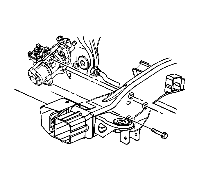
- Raise the vehicle on a hoist. Support the vehicle with suitable safety stands.
- Remove both of the front tire and wheel assemblies. Refer to Tire and Wheel Removal and Installation in Tires and Wheels.
- Remove the engine shield, if equipped. Refer to Engine Protection Shield Replacement in Frame and Underbody.
- Remove the stabilizer shaft. Refer to Stabilizer Shaft Replacement in Front Suspension.
- Place a drain pan under the lines in order to catch the fluid.
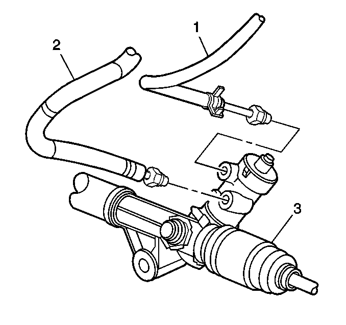
- Remove the power steering high pressure line (2) from the rack and pinion assembly (3).
- Remove the power steering low pressure line (1) from the rack and pinion assembly (3).
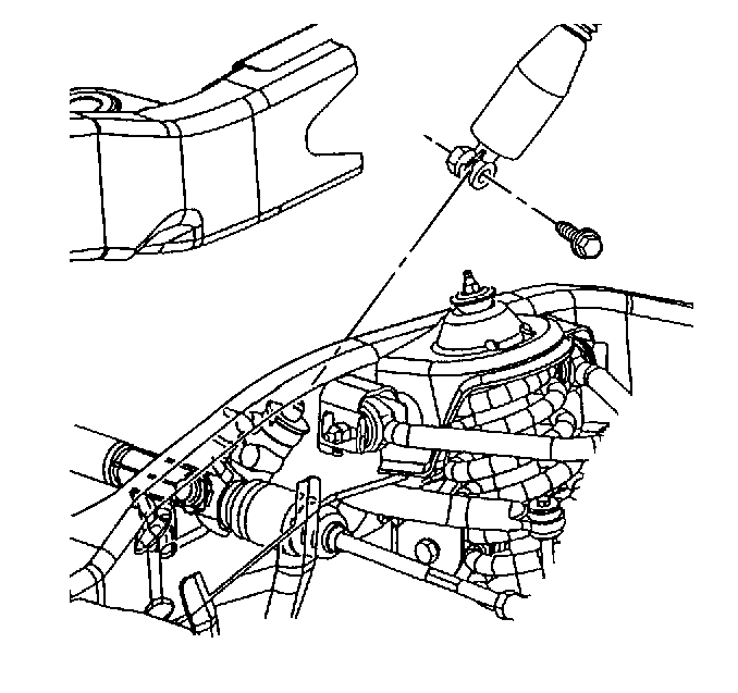
- Remove the coupler clamp bolt from the intermediate shaft.
- Remove the intermediate shaft from the rack and pinion assembly.
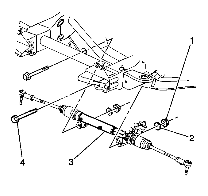
- Remove the rack and pinion assembly mounting nuts (1), the washers (2) and the bolts (4).
- Remove the rack and pinion assembly (3) from the vehicle.
Installation Procedure
- Install the rack and pinion assembly (3) into the vehicle.
- Install the rack and pinion assembly mounting bolts (4), the washers (2) and the nuts (1).
- Install the intermediate shaft to the rack and pinion assembly.
- Install the coupler clamp bolt to the intermediate shaft.
- Install the power steering low pressure hose (1) to the rack and pinion assembly (3).
- Install the power steering high pressure hose (2) to the rack and pinion assembly (3).
- Install the engine protection shield, if equipped. Refer to Engine Protection Shield Replacement in Frame and Underbody.
- Install the stabilizer shaft. Refer to Stabilizer Shaft Replacement in Front Suspension.
- Install both of the front tire and wheel assemblies. Refer to Tire and Wheel Removal and Installation in Tires and Wheels.
- Remove the safety stands.
- Lower the vehicle.
- Bleed the power steering system. Refer to Power Steering System Bleeding .
Notice: Use the correct fastener in the correct location. Replacement fasteners must be the correct part number for that application. Fasteners requiring replacement or fasteners requiring the use of thread locking compound or sealant are identified in the service procedure. Do not use paints, lubricants, or corrosion inhibitors on fasteners or fastener joint surfaces unless specified. These coatings affect fastener torque and joint clamping force and may damage the fastener. Use the correct tightening sequence and specifications when installing fasteners in order to avoid damage to parts and systems.
Tighten
Tighten the nuts to 185 N·m (136 lb ft).
Tighten
Tighten the coupler clamp bolt to 45 N·m (33 lb ft).
Tighten
Tighten the hoses to 27 N·m (28 lb ft).
