Steering Shaft, Lower Bearing, and Jacket - Disassemble - Off Vehicle Floor Shift
Tools Required
| • | J 21854-01 Pivot Pin Remover |
| • | J 41688 Centering Sphere Installer |
- Remove the electronic lock module assembly. Refer to Electronic Column Lock Module - Disassemble - Off Vehicle .
- Remove the tilt spring only. Refer to Tilt Spring - Disassemble - Off Vehicle .
- Inspect the steering column for accident damage. Refer to Steering Column Accident Damage Inspection - Off Vehicle .
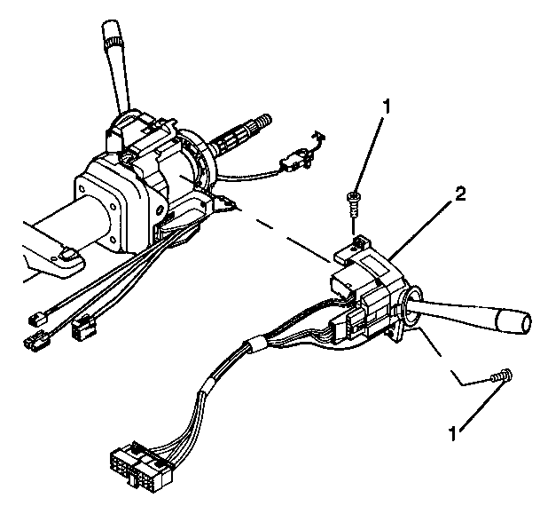
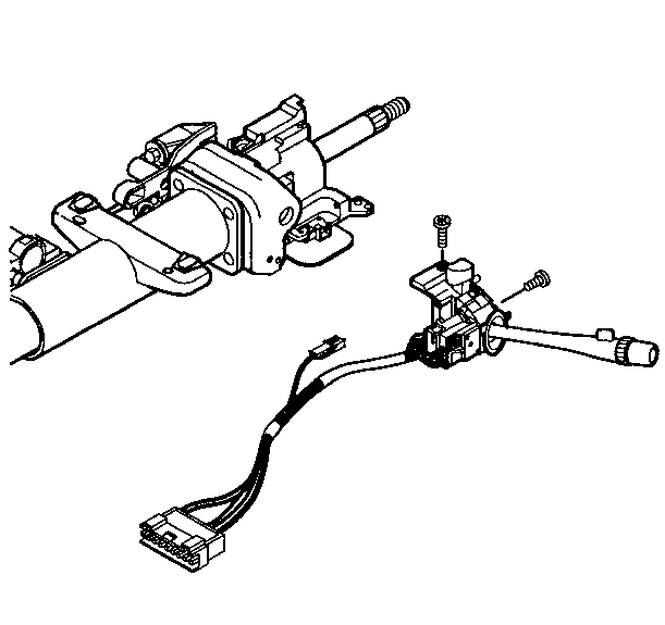
- Remove the 2 pan head tapping screws (1) from the turn signal and multifunction switch assembly (2).
- Remove the turn signal and multifunction switch assembly (2).
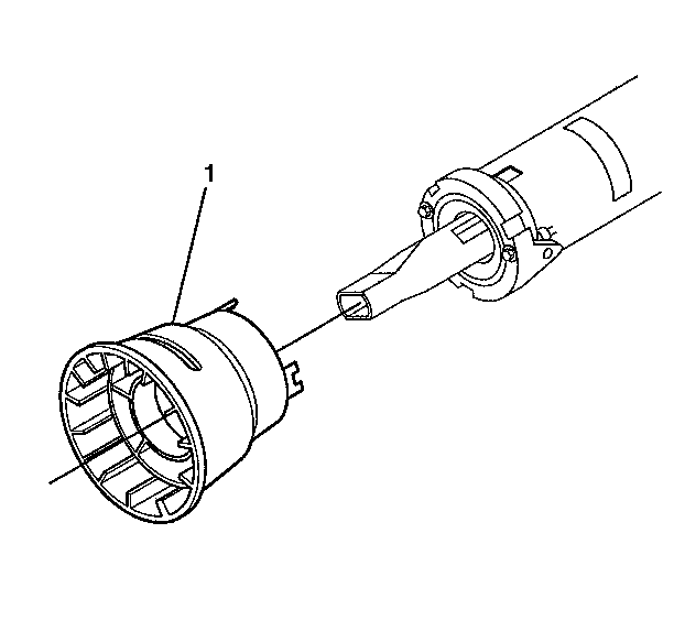
- Remove the adapter and bearing assembly (1) from the steering column shaft assembly.
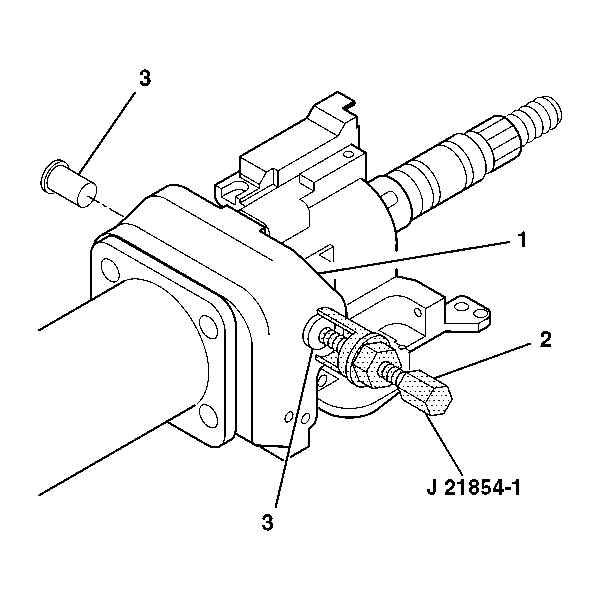
- Remove the 2 pivot pins (3) from the steering column tilt head assembly (1) by using J 21854-01 .
- Install the tilt lever into the steering column tilt head assembly (1).
- Pull back on the tilt lever and at the same time pull the steering column tilt head assembly (1) down and away from the steering column.
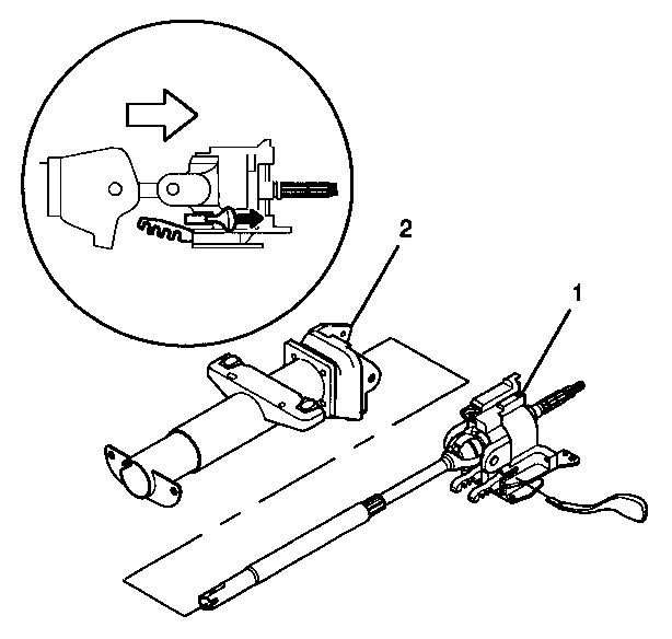
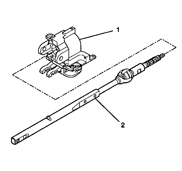
- Remove the steering column tilt head assembly (1) with the steering column shaft assembly from the steering column support assembly (2).
- Remove the tilt lever.
- Remove the steering column shaft assembly (2) from the steering column tilt head assembly (1).
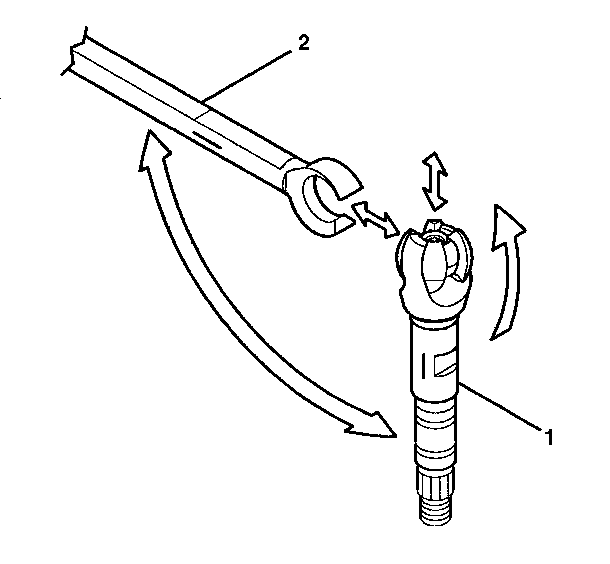
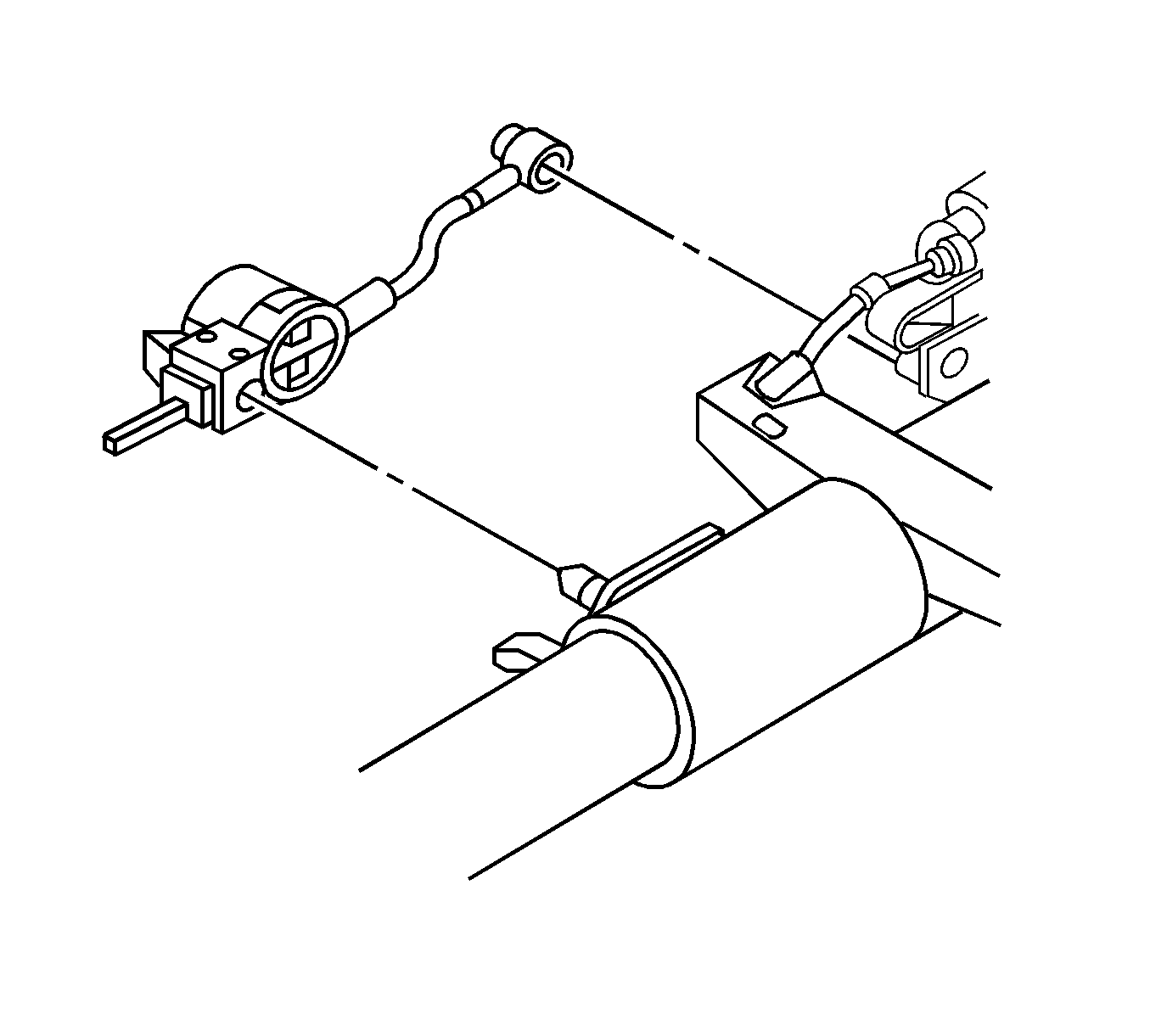
- Tilt the race and upper shaft assembly (1) 90 degrees to the lower shaft assembly (2).
- Disengage the race and upper shaft assembly (1) from the lower shaft assembly (2).
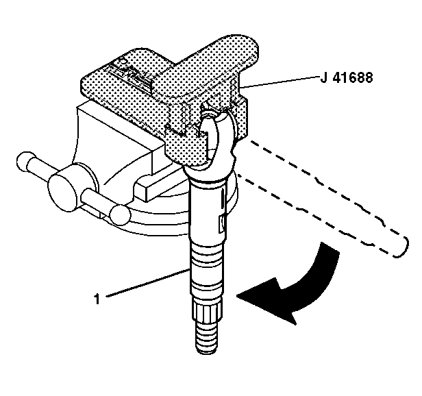
- Insert the race and upper shaft assembly (1) into J 41688 .
- Insert J 41688 into a vise.
- Rotate the driver 90 degrees in the counterclockwise direction in order to disengage the centering sphere from the race and upper shaft assembly.
- Remove the race and upper shaft assembly from J 41688 .
- Remove the shaft preload spring and the centering sphere fromJ 41688 .
- If necessary, discard the old centering sphere and the old shaft preload spring.
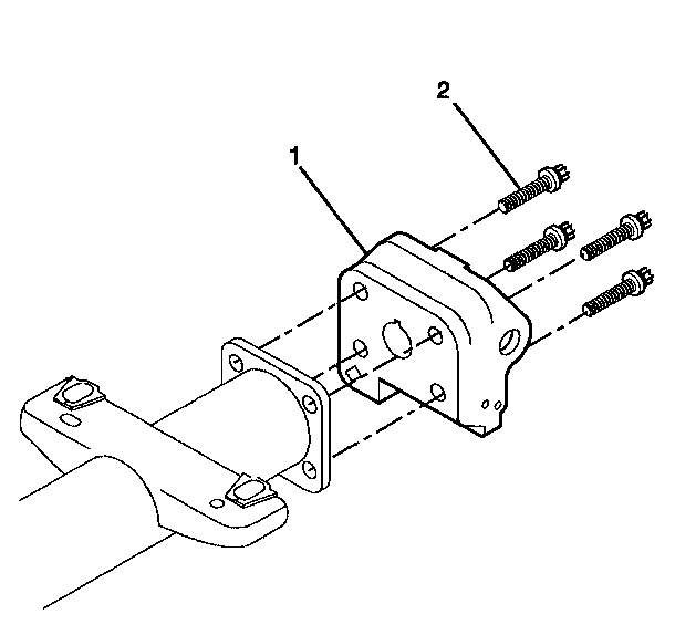
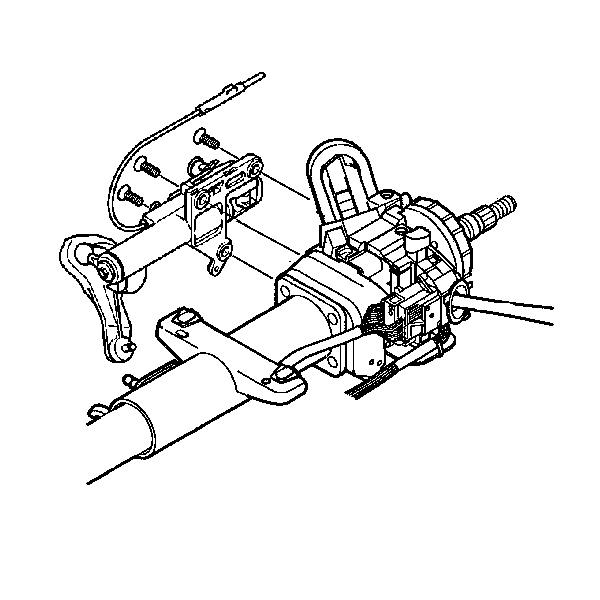
- Remove the 4 TORX® head screws (2) from the steering column support assembly (1).
- Discard the 4 TORX® head screws.
- Remove the steering column support assembly (1) from the steering column jacket assembly.
Important: Mark the race and upper shaft assembly and the lower shaft assembly before disassembly. Failure to assemble the race and upper shaft assembly and the lower shaft assembly correctly will cause the steering wheel to be turned 180 degrees.
Steering Shaft, Lower Bearing, and Jacket - Disassemble - Off Vehicle Column Shift
Tools Required
| • | J 21854-01 Pivot Pin Remover |
| • | J 41688 Centering Sphere Installer Tool |
- Remove the electronic lock module assembly. Refer to Electronic Column Lock Module - Disassemble - Off Vehicle .
- Remove the tilt spring assembly only. Refer to Tilt Spring - Disassemble - Off Vehicle .
- Inspect the steering column for accident damage. Refer to Steering Column Accident Damage Inspection - Off Vehicle .
- Remove the 2 TORX® screws from the turn signal and multifunction switch assembly.
- Remove the automatic transmission shift lock control in the following way:
- Remove the 3 TORX® screws from the linear shift assembly.
- Remove the adapter and bearing assembly (1) from the steering column shaft assembly.
- Remove the 2 pivot pins (3) from the steering column tilt head assembly (1) by using J 21854-01 .
- Install the tilt lever into the steering column tilt head assembly (1).
- Pull back on the tilt lever and at the same time pull the steering column tilt head assembly (1) down and away from the steering column.
- Remove the steering column tilt head assembly (1) with the steering column shaft assembly from the steering column jacket assembly (2).
- Remove the tilt lever.
- Remove the steering column shaft assembly (2) from the steering column tilt head assembly (1).
- Tilt the steering column shaft assembly (1) 90 degrees to the lower shaft assembly (2).
- Disengage the race and upper shaft assembly (1) from the lower shaft assembly (2).
- Insert the race and upper shaft assembly (1) into J 41688 .
- Insert J 41688 into a vise.
- Rotate the driver 90 degrees in the counterclockwise direction in order to disengage the centering sphere from the race and upper shaft assembly.
- Remove the race and upper shaft assembly (1) from J 41688 .
- Remove the shaft preload spring and the centering sphere fromJ 41688 .
- If necessary, discard the old centering sphere and the old shaft preload spring.
- Remove the 4 TORX® head screws (2) from the steering column support assembly (1).
- Discard the 4 TORX® head screws.
- Remove the steering column support assembly (1) from the steering column jacket assembly.
Remove the turn signal and multifunction switch assembly.
| 5.1. | Put the shift lever clevis into the NEUTRAL position. |
| 5.2. | Use a small screwdriver to pry the automatic transmission shift lock control away from the steering column jacket assembly and the cable shift cam assembly. |
Remove the linear shift assembly from the steering column support assembly.
Important: Mark the race and upper shaft assembly and the lower shaft assembly before disassembly. Failure to assemble the race and upper shaft assembly and the lower shaft assembly correctly will cause the steering wheel to be turned 180 degrees.
Steering Shaft, Lower Bearing, and Jacket - Disassemble - Off Vehicle Export
Tools Required
| • | J 21854-01 Pivot Pin Remover |
| • | J 41688 Centering Sphere Installer Tool |
- Remove the electronic lock module assembly. Refer to Electronic Column Lock Module - Disassemble - Off Vehicle .
- Remove the tilt spring assembly only. Refer to Tilt Spring - Disassemble - Off Vehicle .
- Inspect the steering column for accident damage. Refer to Steering Column Accident Damage Inspection - Off Vehicle .
- Remove the 2 TORX® screws from the turn signal and multifunction switch assembly.
- Remove the 3 TORX® screws from the linear shift assembly.
- Remove the adapter and bearing assembly (1) from the steering column shaft assembly.
- Remove the 2 pivot pins (3) from the steering column tilt head assembly (1) by using J 21854-01 .
- Install the tilt lever into the steering column tilt head assembly (1).
- Pull back on the tilt lever and at the same time pull the steering column tilt head assembly (1) down and away from the steering column.
- Remove the steering column tilt head assembly (1) with the steering column shaft assembly from the steering column jacket assembly (2).
- Remove the tilt lever.
- Remove the steering column shaft assembly (2) from the steering column tilt head assembly (1).
- Tilt the race and upper shaft assembly (1) 90 degrees to the lower shaft assembly (2).
- Disengage the race and upper shaft assembly (1) from the lower shaft assembly (2).
- Insert the race and upper shaft assembly (1) into J 41688 .
- Insert J 41688 into a vise.
- Rotate the driver 90 degrees in the counterclockwise direction in order to disengage the centering sphere from the race and upper shaft assembly.
- Remove the race and upper shaft assembly (1) from J 41688 .
- Remove the shaft preload spring and the centering sphere fromJ 41688 .
- If necessary, discard the old centering sphere and the old shaft preload spring.
- Remove the 4 TORX® head screws (2) from the steering column support assembly (1).
- Discard the 4 TORX® head screws.
- Remove the steering column support assembly (1) from the steering column jacket assembly.
Remove the turn signal and multifunction switch assembly.
Remove the linear shift assembly from the steering column support assembly.
Important: Mark the race and upper shaft assembly and the lower shaft assembly before disassembly. Failure to assemble the steering column shaft assembly and the lower shaft assembly correctly will cause the steering wheel to be turned 180 degrees.
