For 1990-2009 cars only
Removal Procedure
Caution: This vehicle is equipped with a Supplemental Inflatable Restraint (SIR) System. Failure to follow the correct procedure could cause the following conditions:
• Air bag deployment • Personal injury
In order to avoid the above conditions, observe the following guidelines:
• Unnecessary SIR system repairs • Refer to SIR Component Views in order to determine if you are performing service on or near the SIR components or the SIR wiring. • If you are performing service on or near the SIR components or the SIR wiring, disable the SIR system. Refer to Disabling the SIR System.
- Disable the SIR system. Refer to Disabling the SIR System .
- Remove the instrument panel trim bezel. Refer to Instrument Panel Cluster Trim Plate Bezel Replacement in Instrument Panel, Gages and Console.
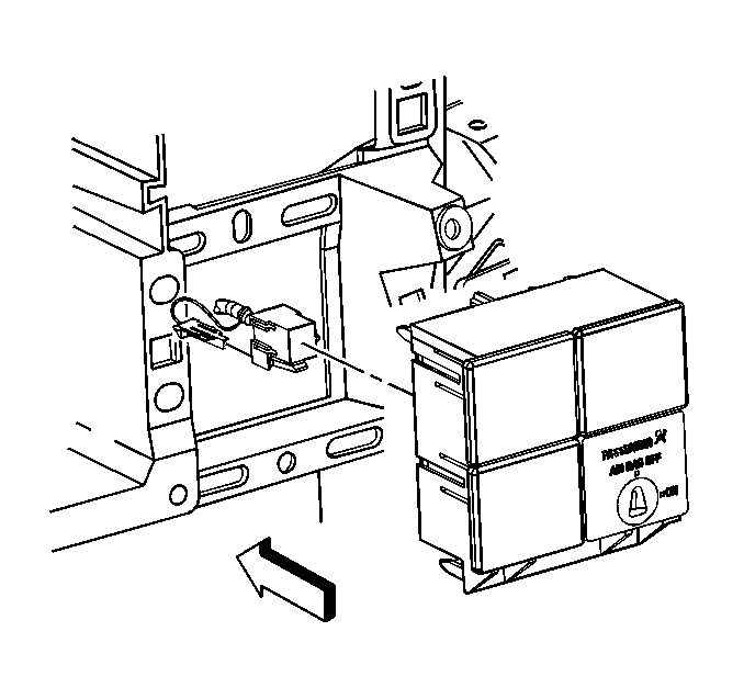
- Remove the IP module switch from the lower right opening of the switch plate panel.
- Disconnect the IP module switch electrical connector.

Installation Procedure
- Connect the IP module switch electrical connector.
- Install the IP module switch into the lower right opening of the switch plate panel.
- Install the instrument panel trim bezel. Refer to Instrument Panel Cluster Trim Plate Bezel Replacement in Instrument Panel, Gages and Console.
- Enable the SIR system. Refer to Enabling the SIR System .

