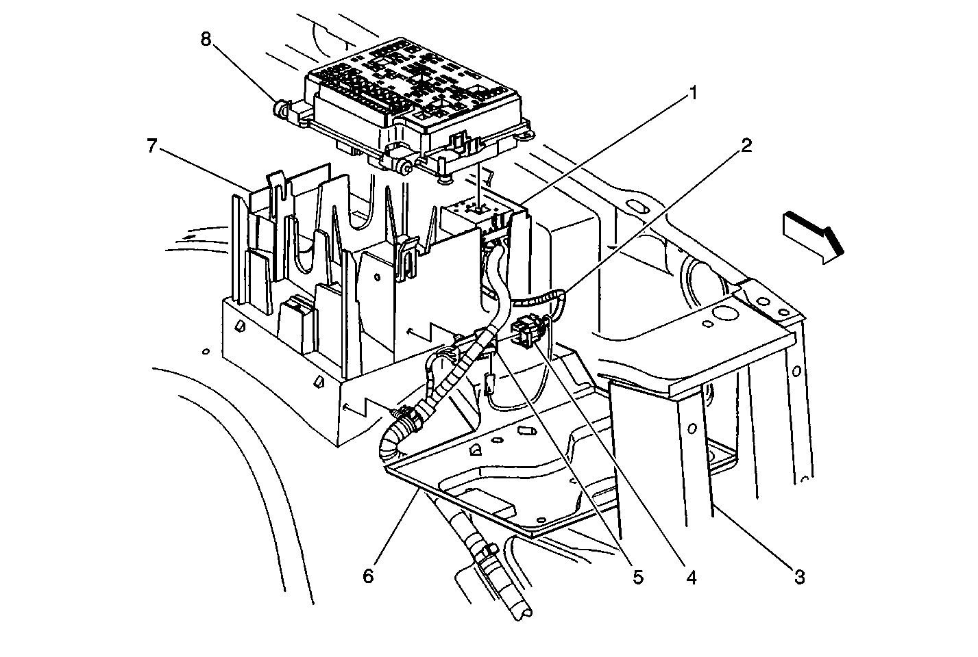
| Figure 1: |
Engine Wiring Harness Junction Block
|
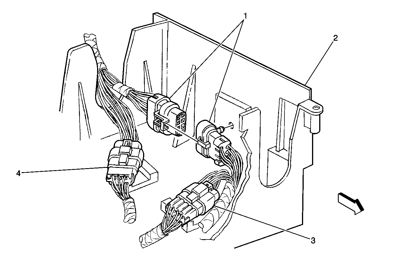
| Figure 2: |
Inline Connectors Under the Engine Wiring Junction Block
|
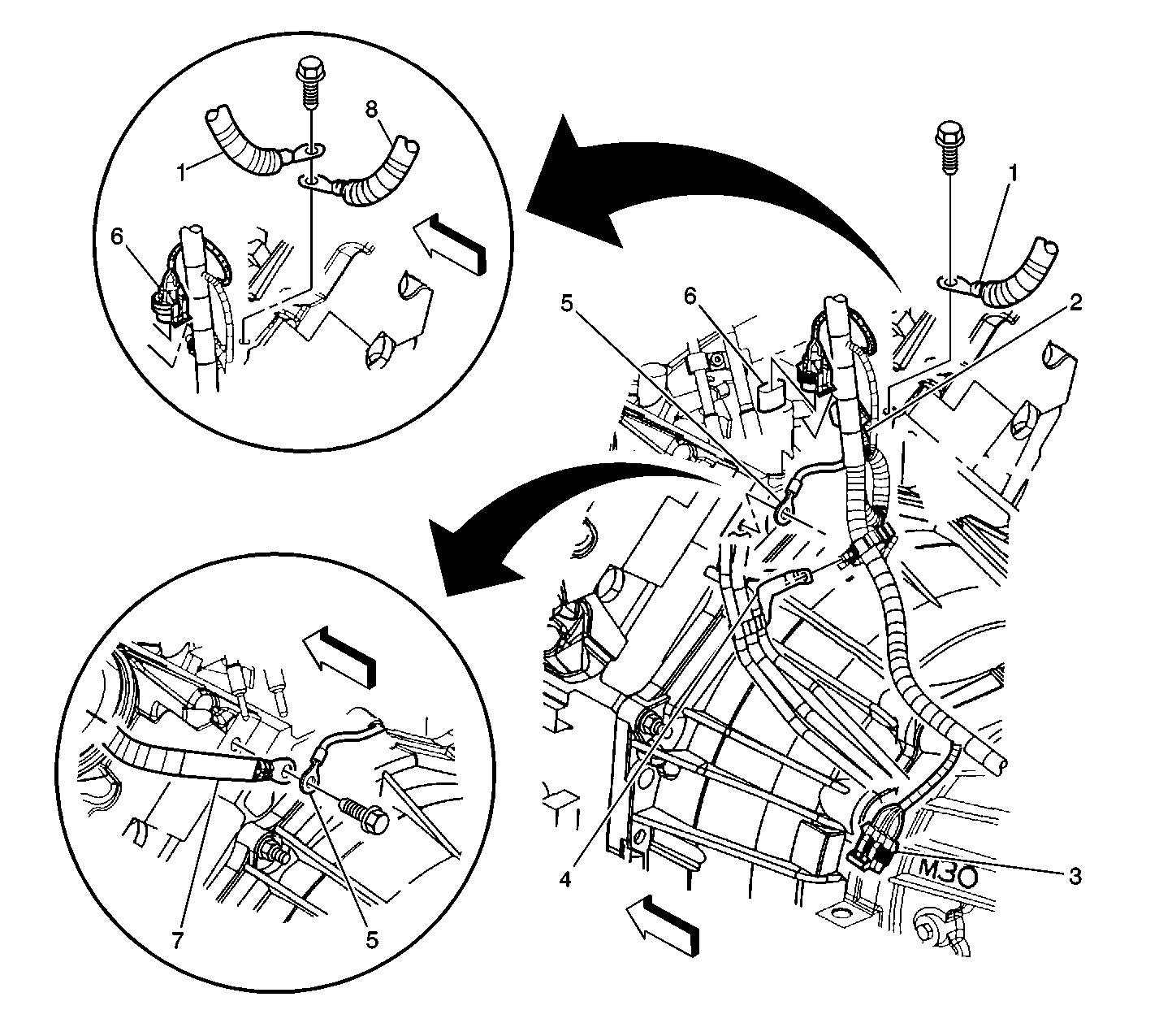
| Figure 3: |
Lower LR of the Engine Components (4.8L/5.3L/6.0L)
|
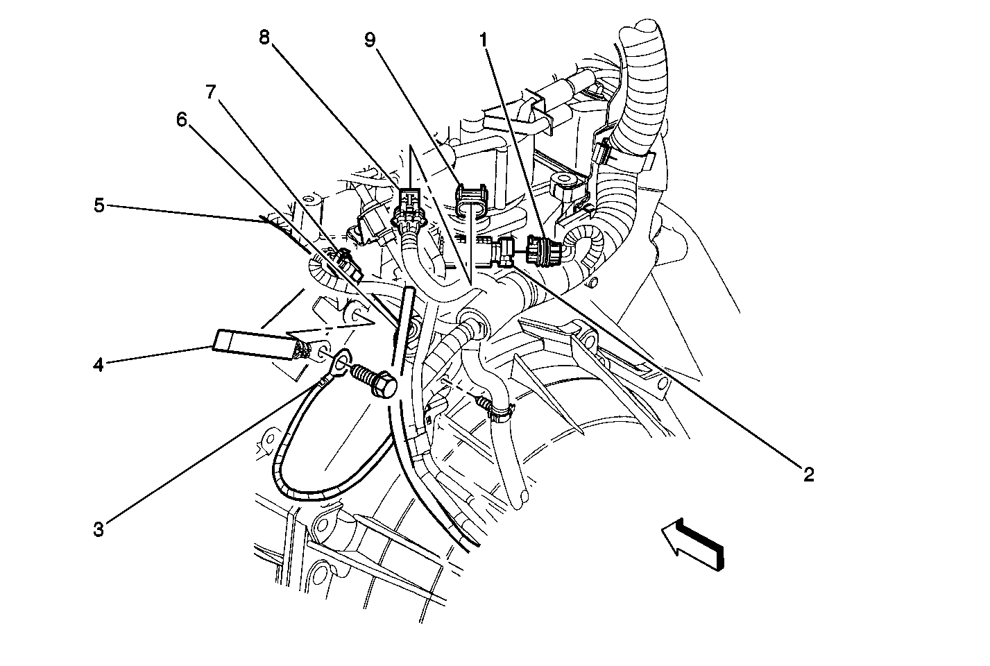
| Figure 4: |
LH Rear View of Engine-4.3L
|
| Figure 5: |
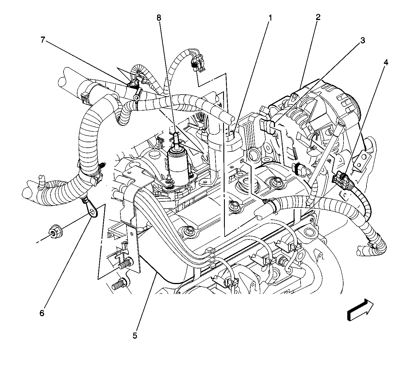
Right Side of the Engine Components (4.3L)
|
| Figure 6: |
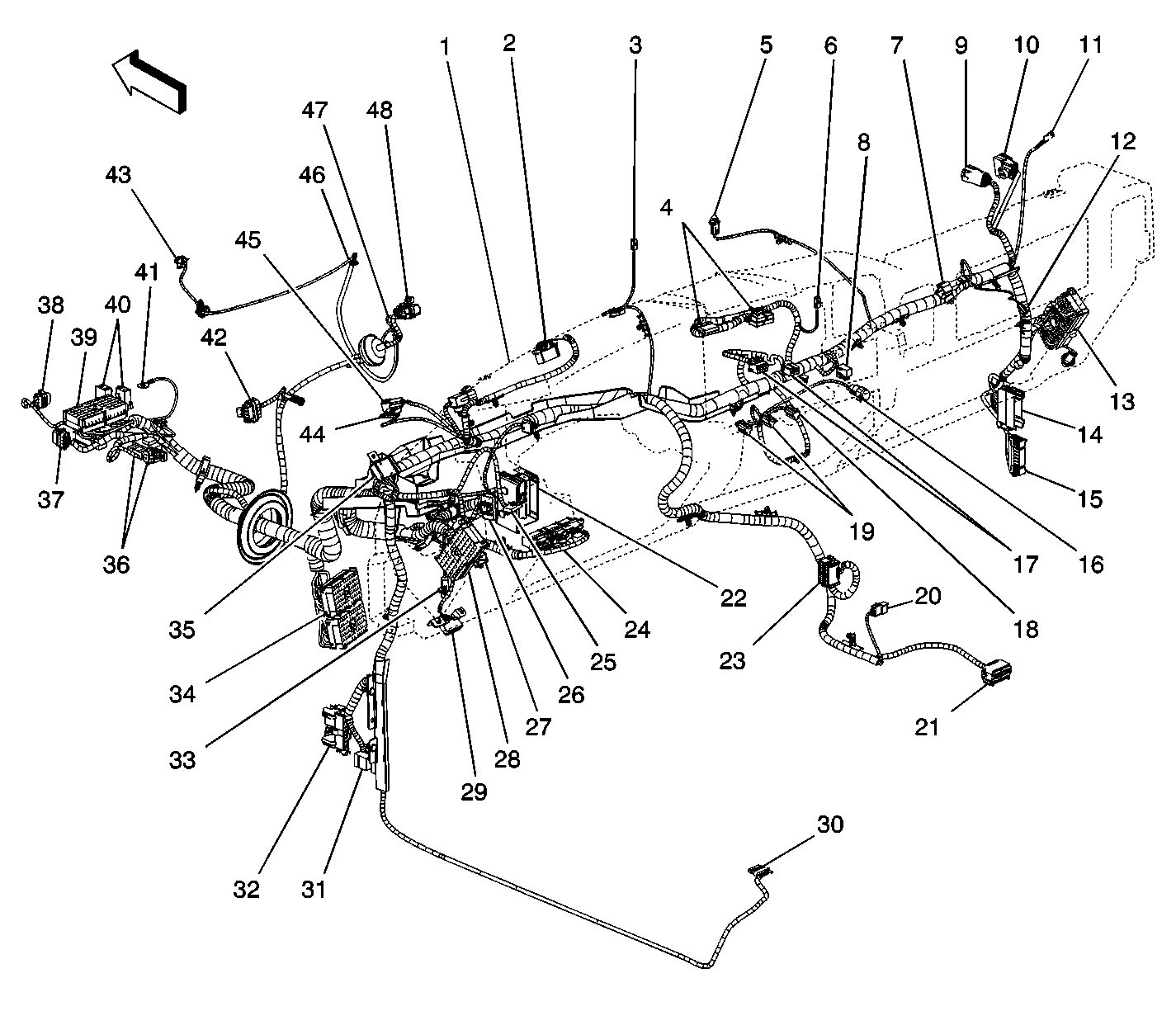
Instrument Panel Harness Routing View
|
| Figure 7: |
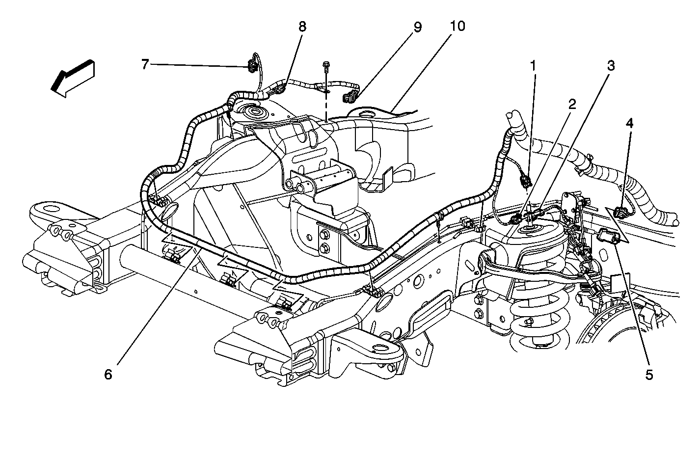
Chassis Wiring Harness to Front Frame (25 Series 3/4 ton)
|
| Figure 8: |
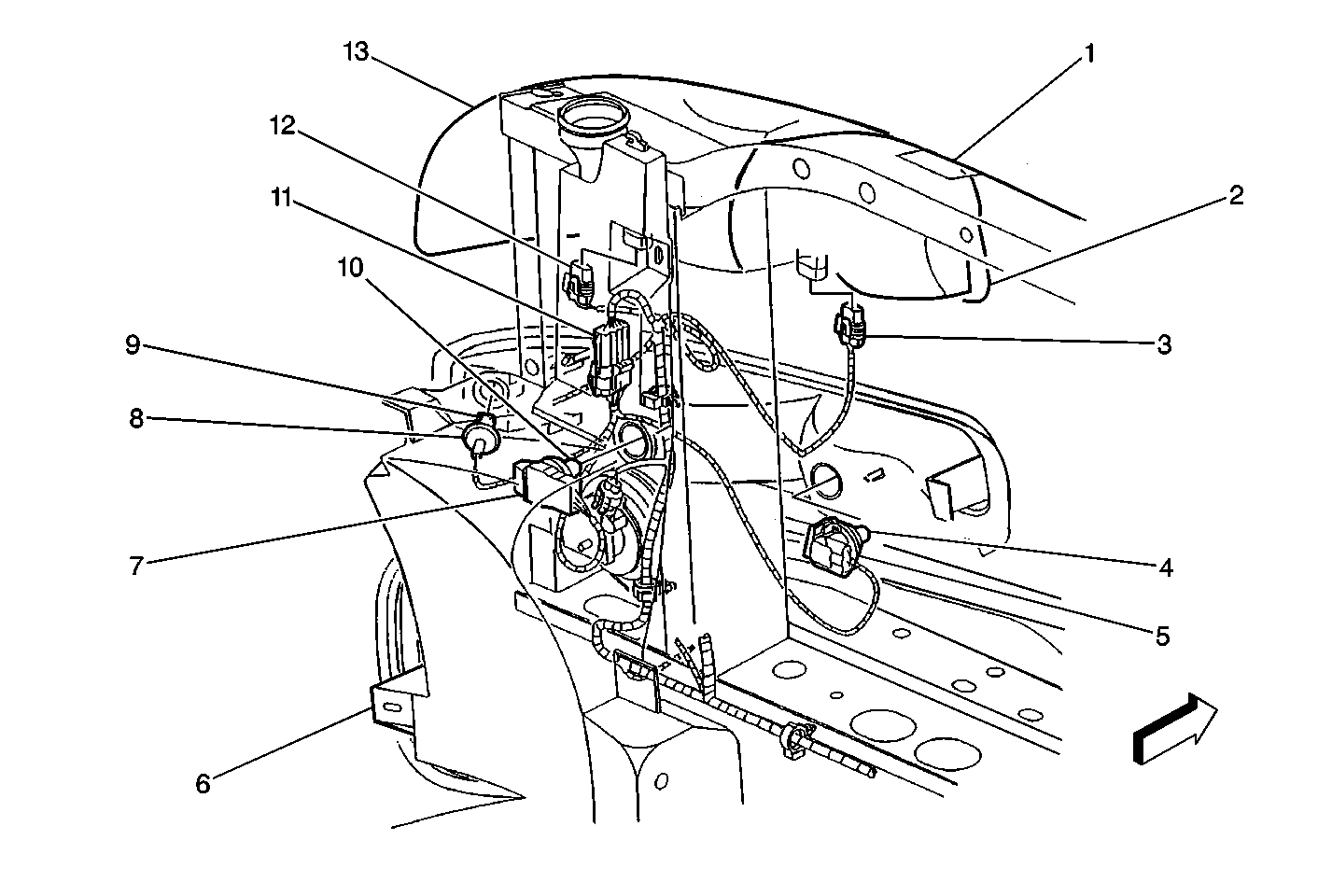
LH Front of Vehicle
|
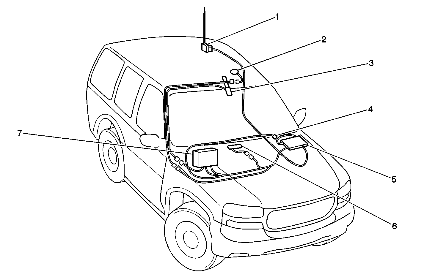
| Figure 9: |
OnStar® Component Locations
|
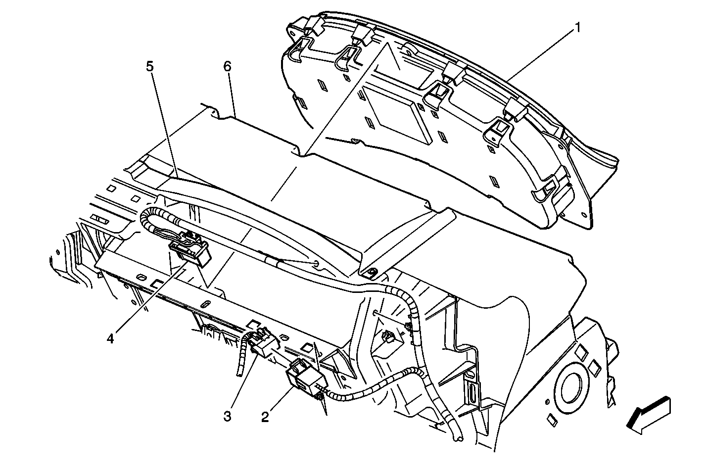
| Figure 10: |
Instrument Cluster
|
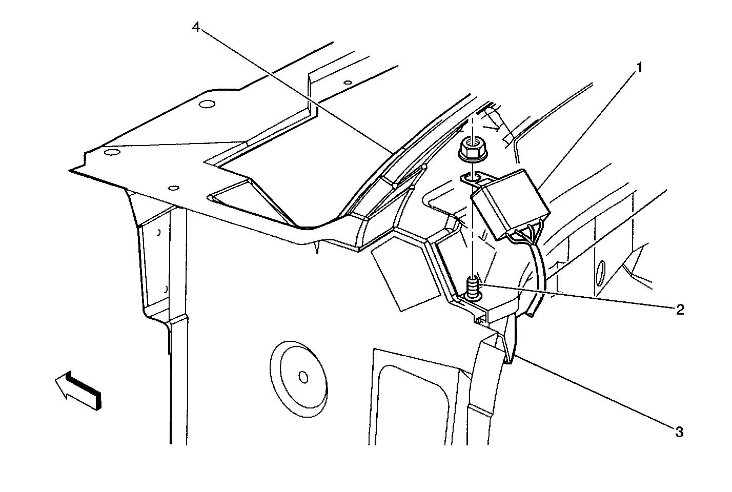
| Figure 11: |
Upper Left of the I/P Components
|
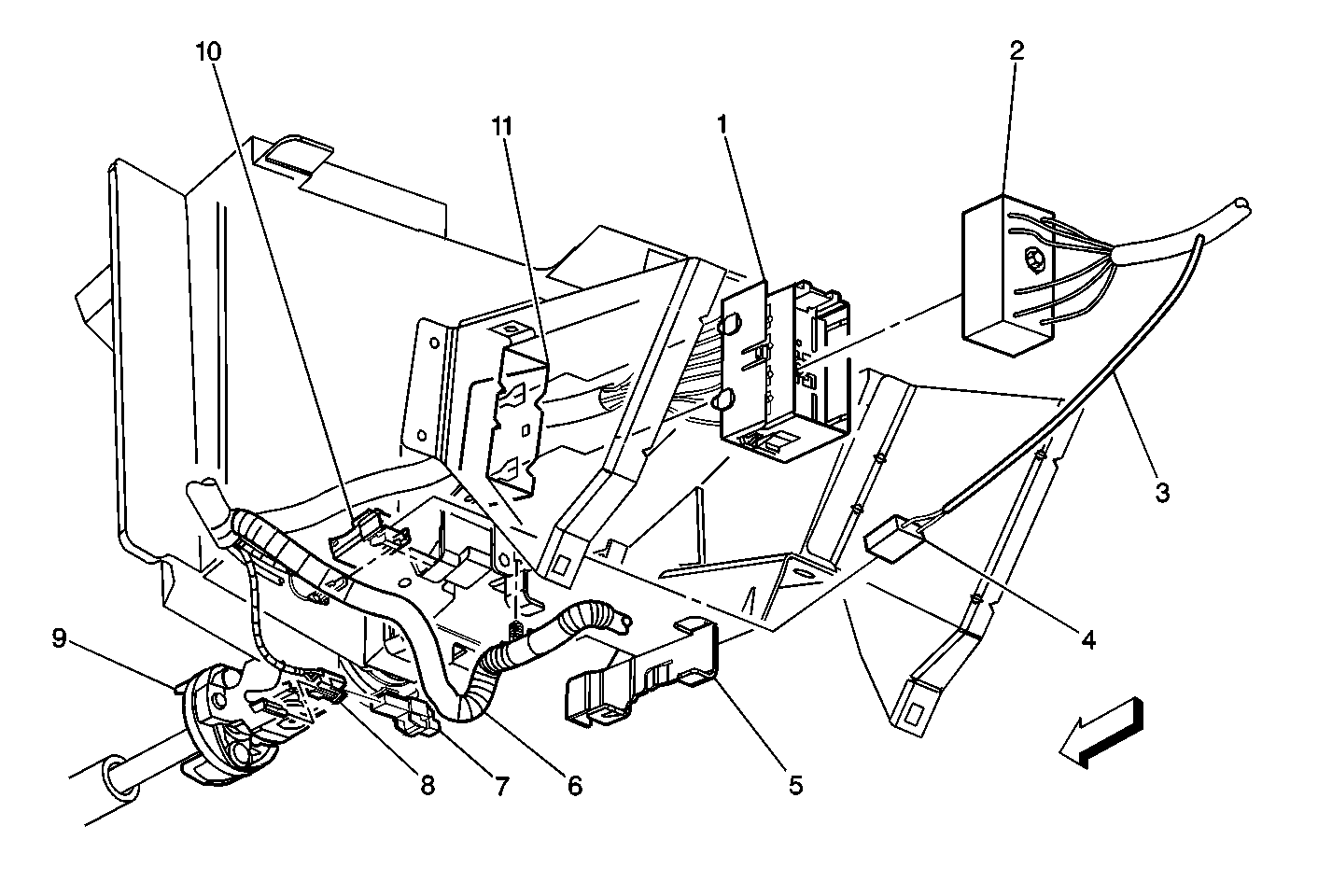
| Figure 12: |
Lower Steering Column Connectors
|
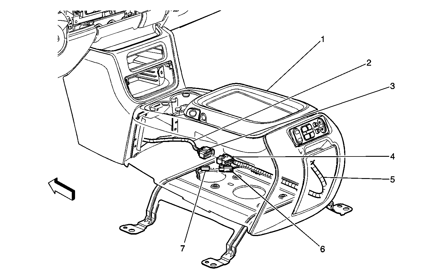
| Figure 13: |
Center Console Wiring (2 of 2)
|
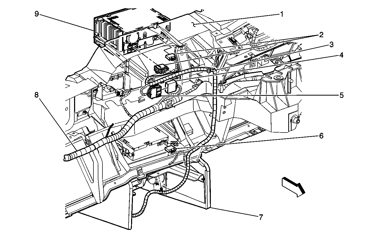
| Figure 14: |
Behind the Center of the I/P
|
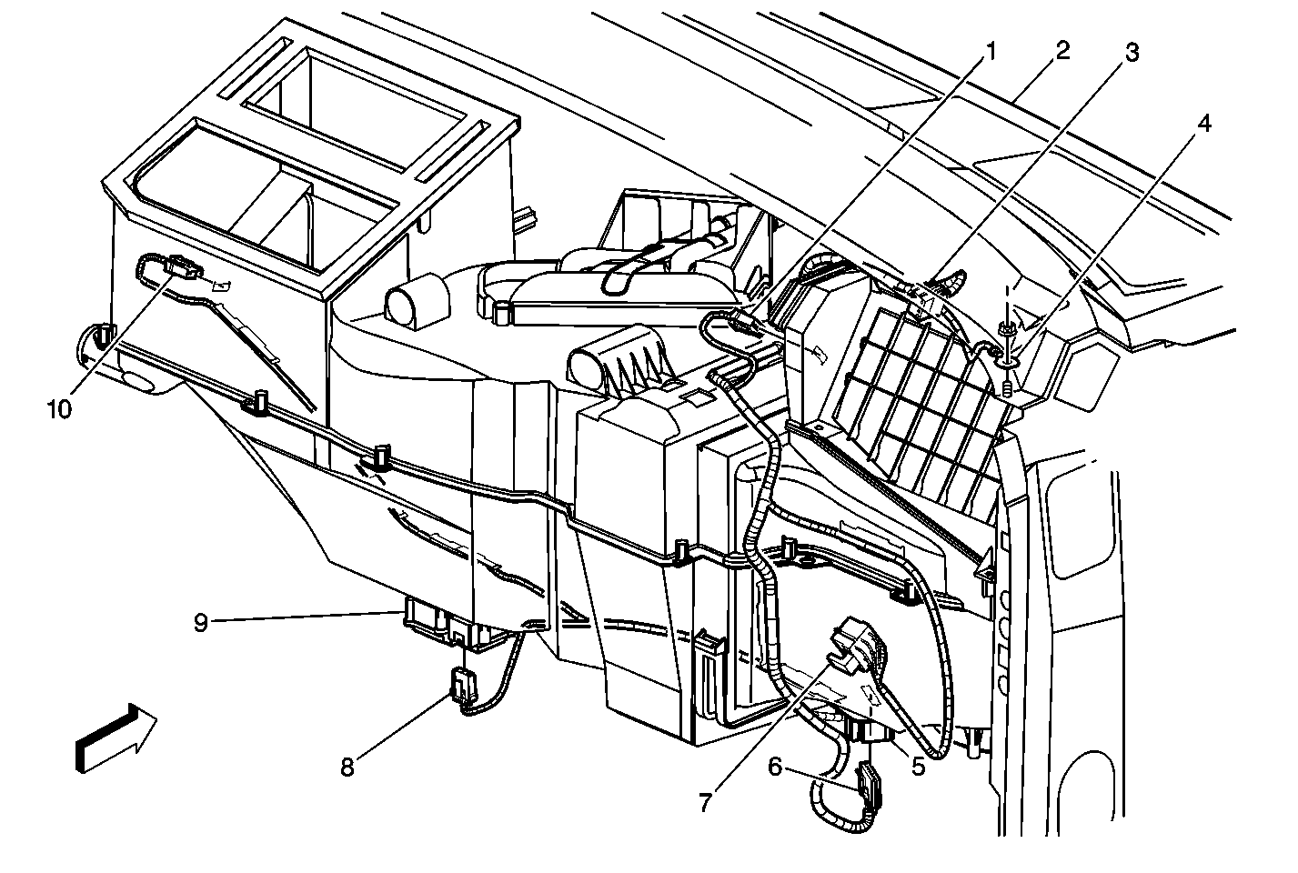
| Figure 15: |
HVAC Module Assembly (Connections)
|
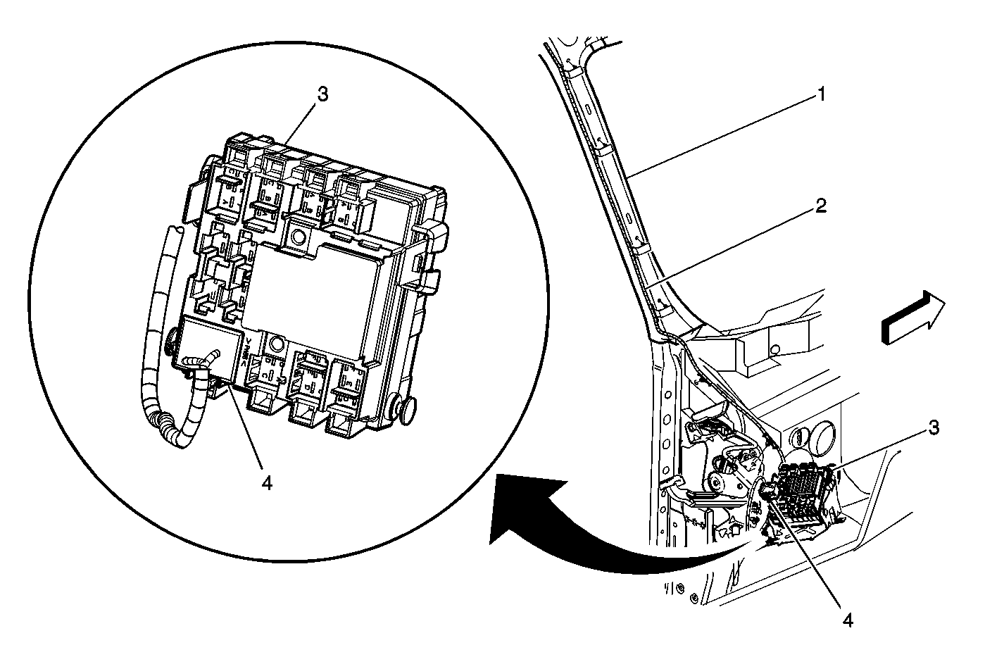
| Figure 16: |
Headliner Harness to Body Wiring Junction Block
|
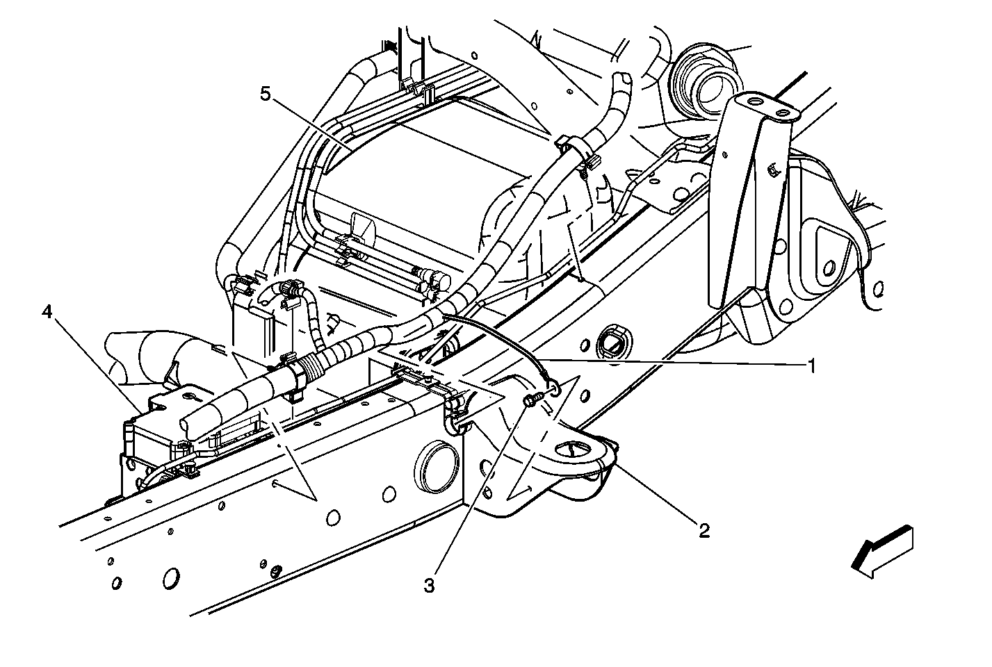
| Figure 17: |
Left Side Frame Rail -- Brake Components
|
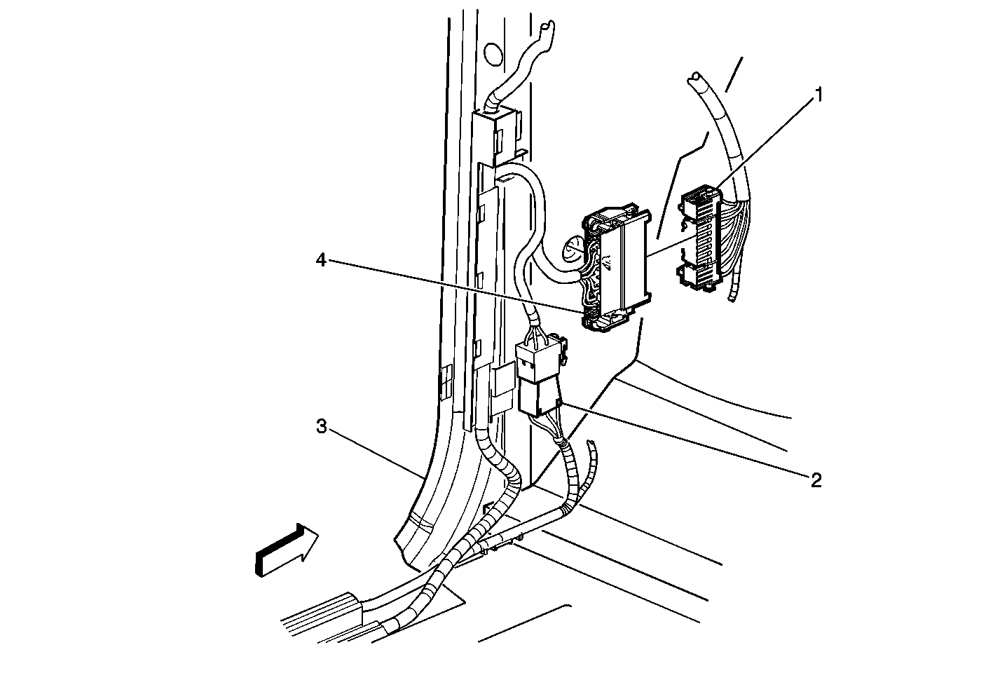
| Figure 18: |
Left Kick Panel (1 of 2)
|
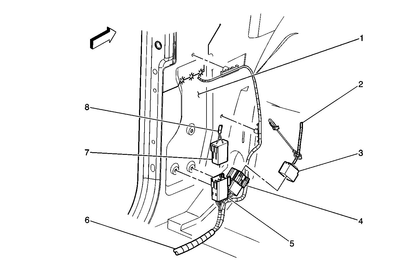
| Figure 19: |
Left Kick Panel (2 of 2)
|
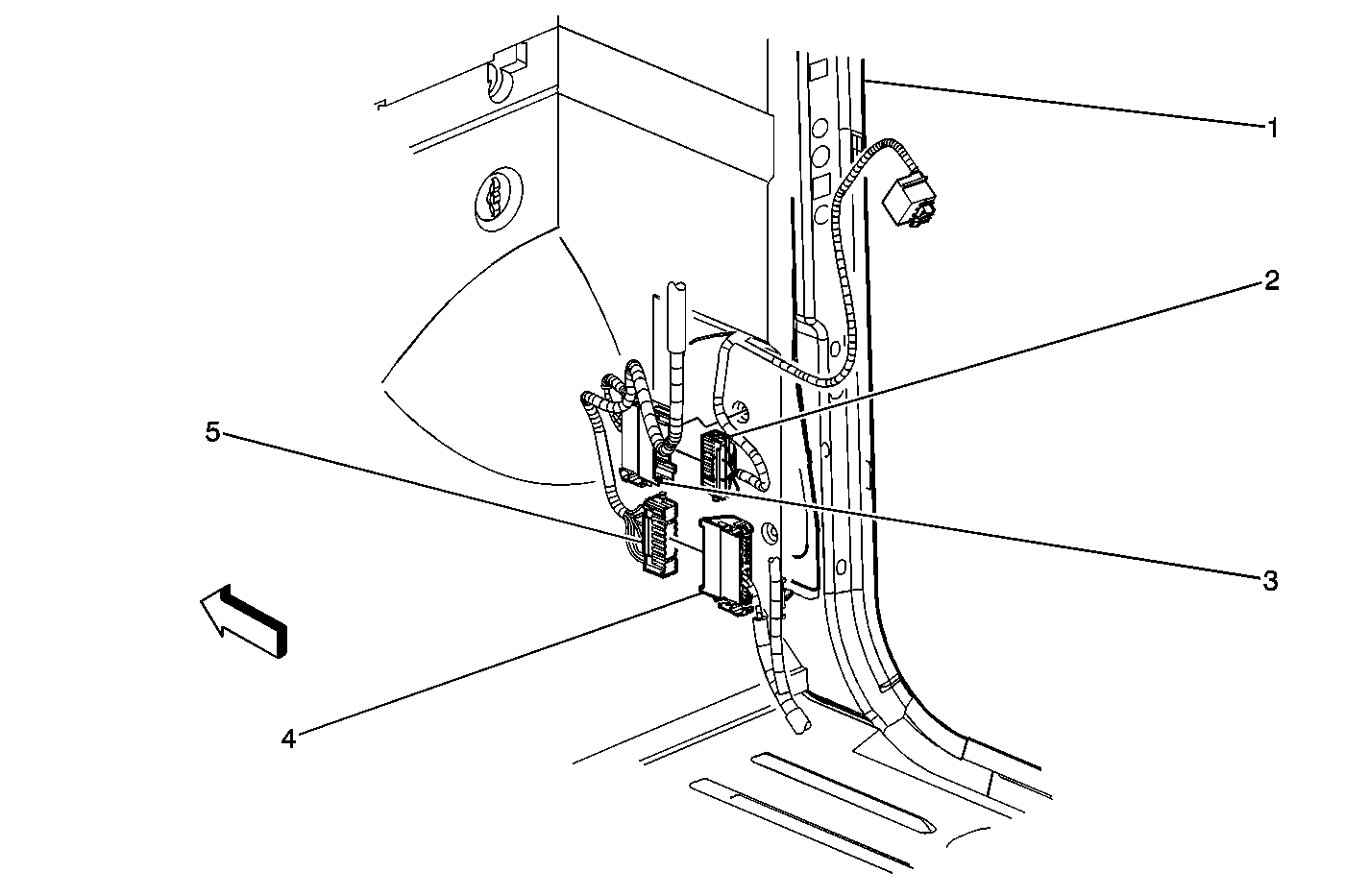
| Figure 20: |
Right Kick Panel (2 of 2)
|
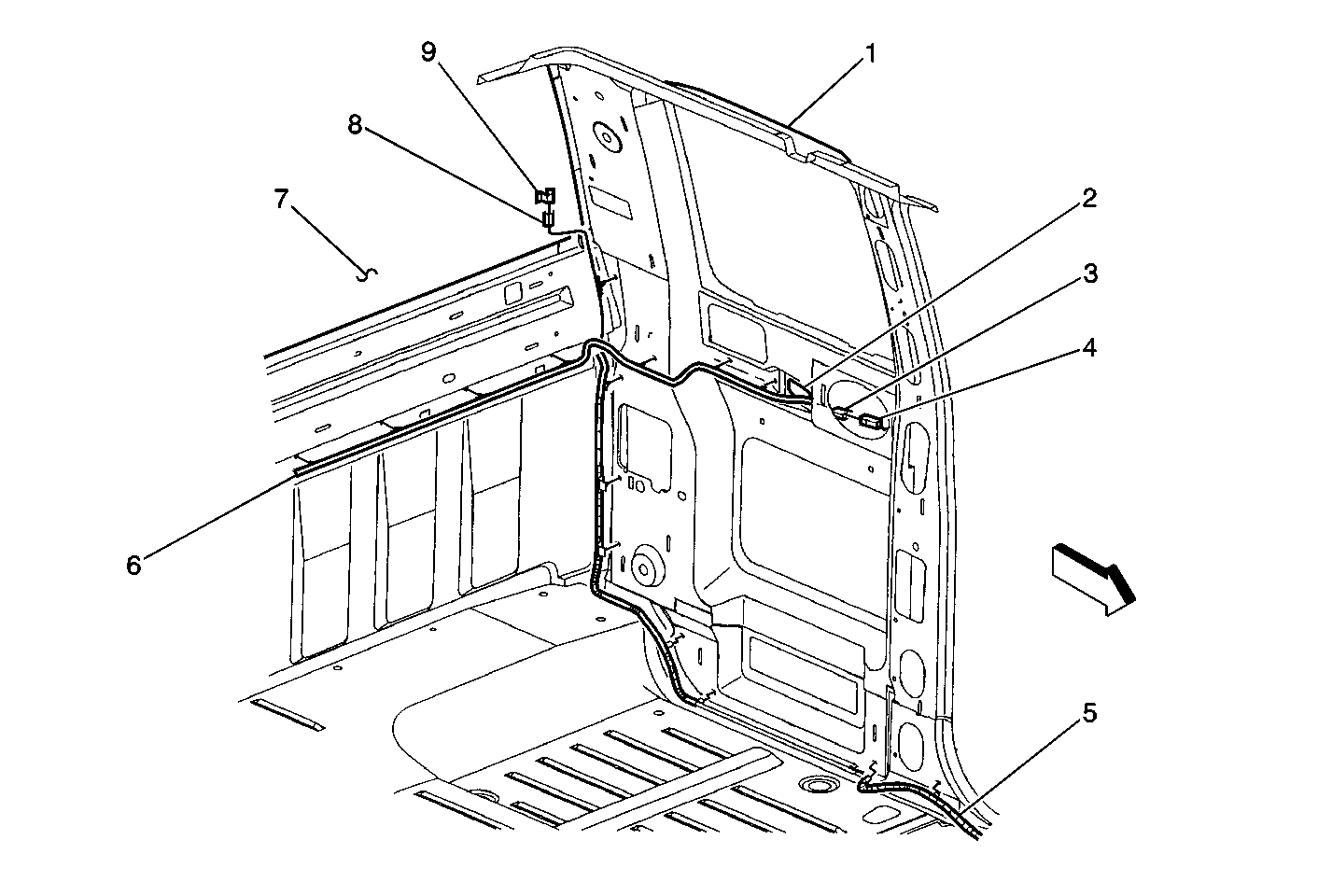
| Figure 21: |
LH Rear of Passenger Compartment
|
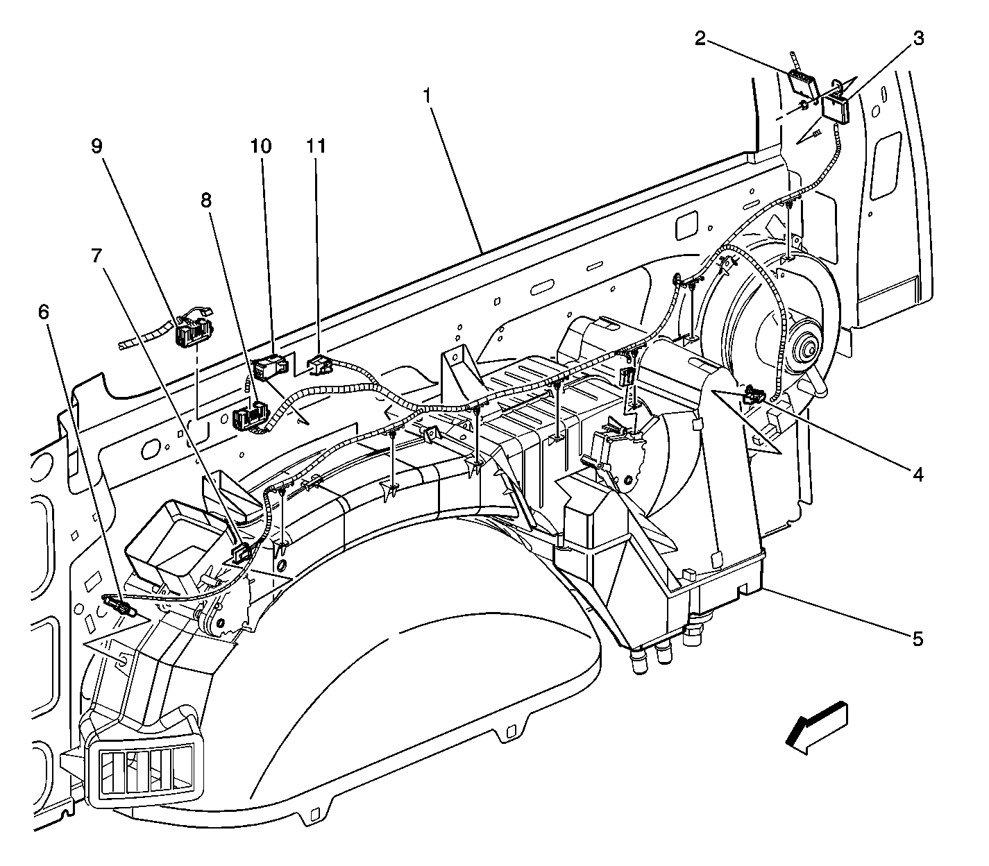
| Figure 22: |
Rear HVAC Harness
|
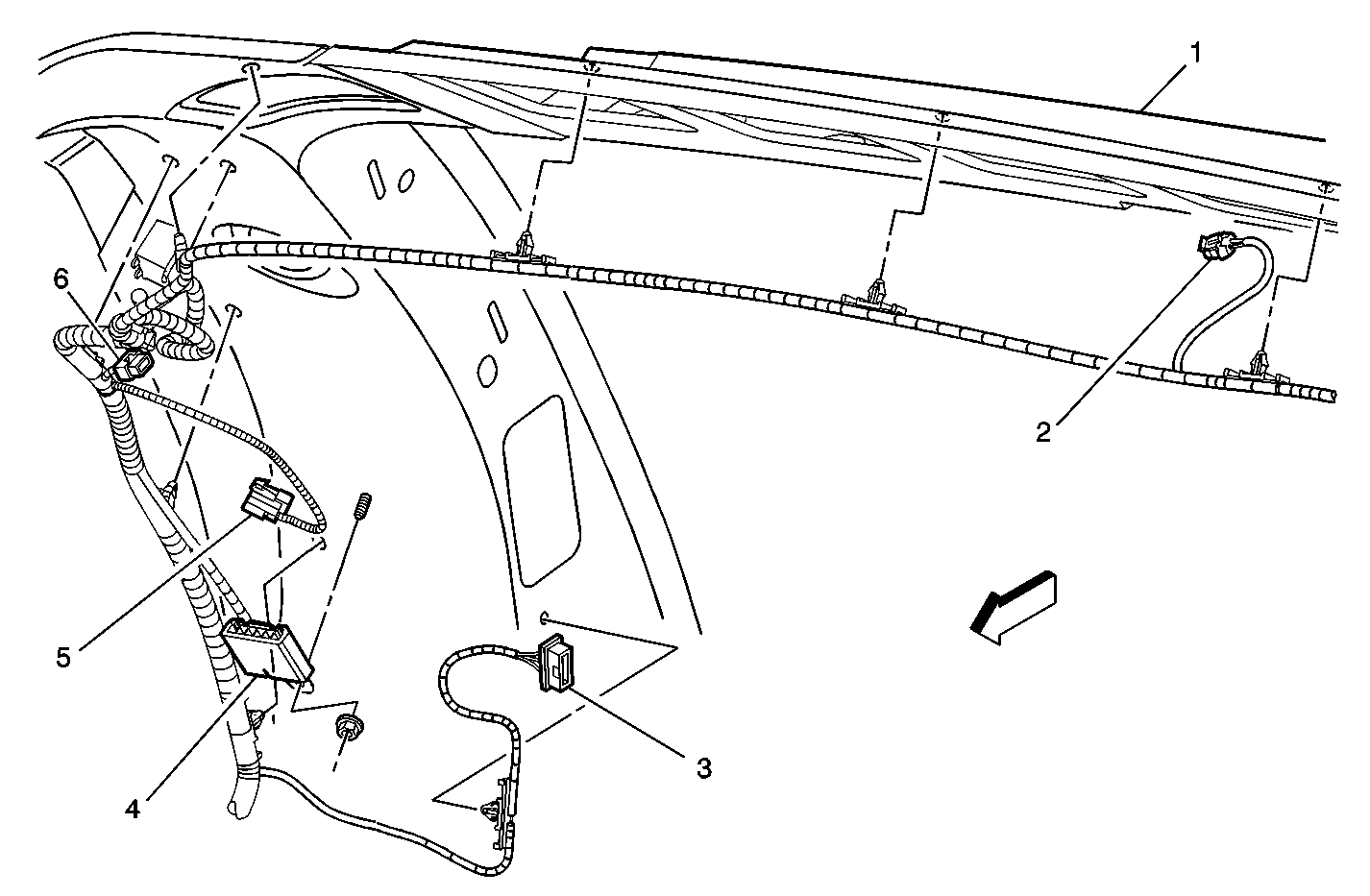
| Figure 23: |
RR D-Pilar Wiring (Utility)
|
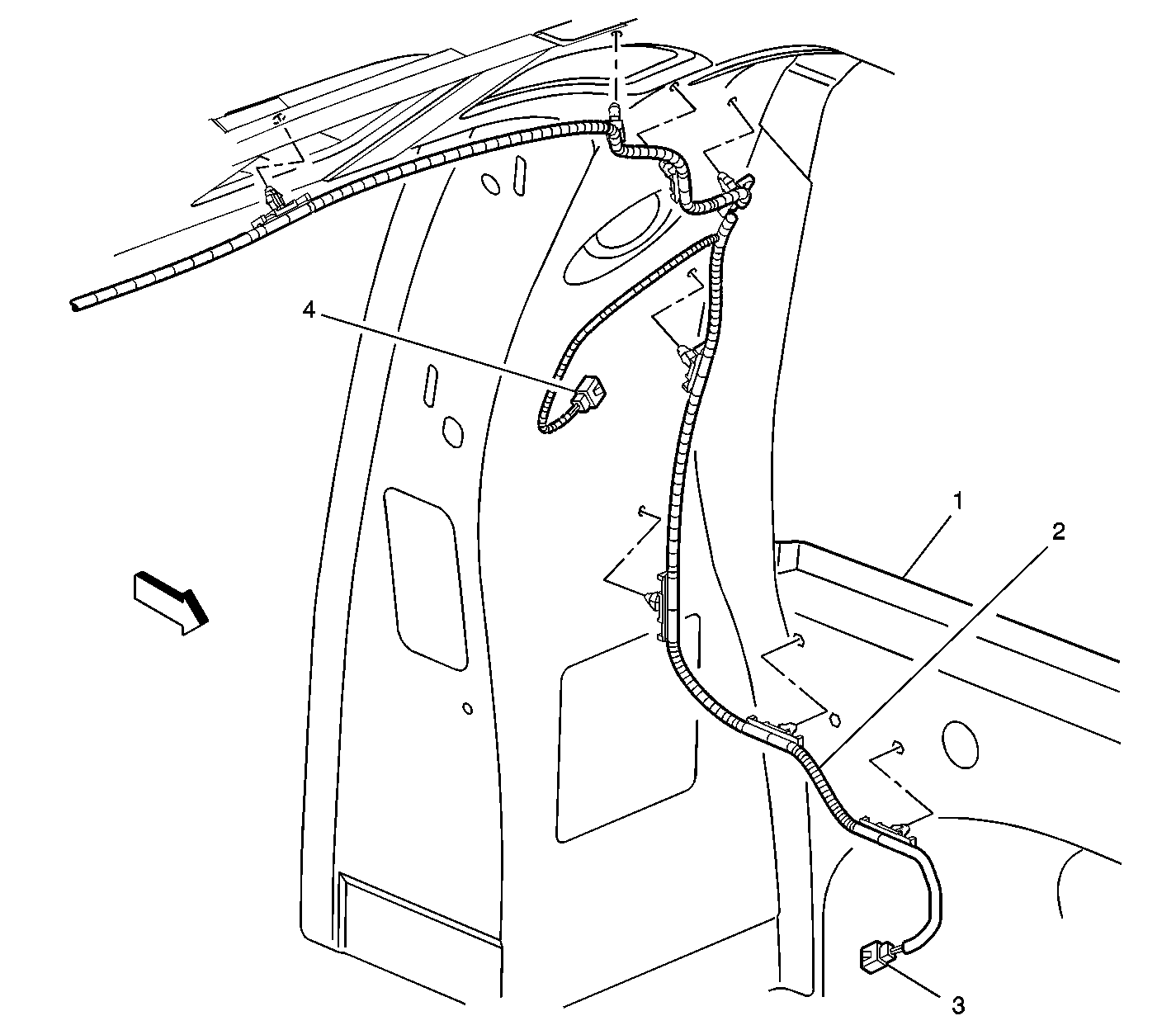
| Figure 24: |
LR D-Pillar Wiring (Utility)
|
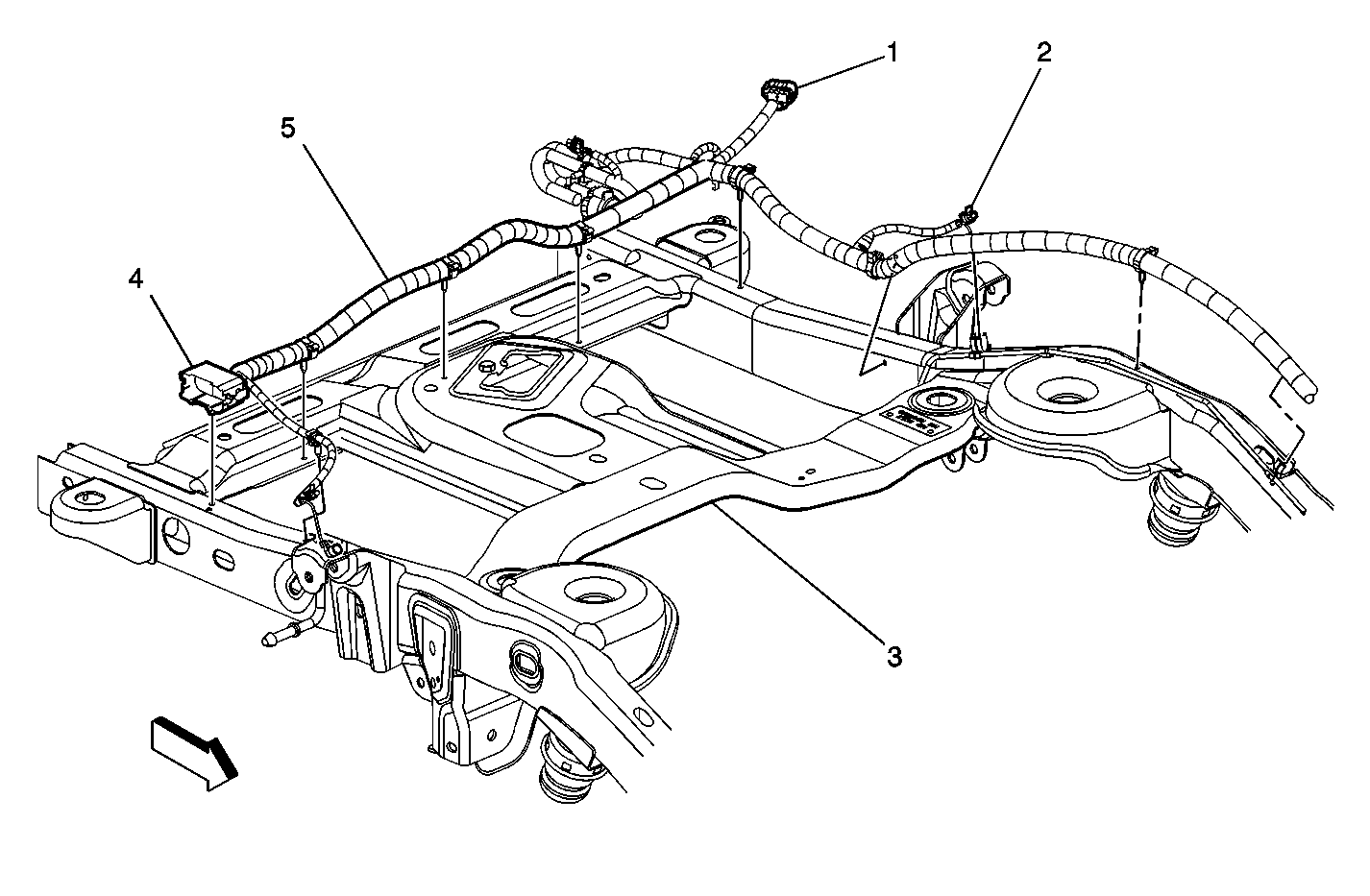
| Figure 25: |
Chassis Wiring Harness to Rear Side Rail -- LH
|
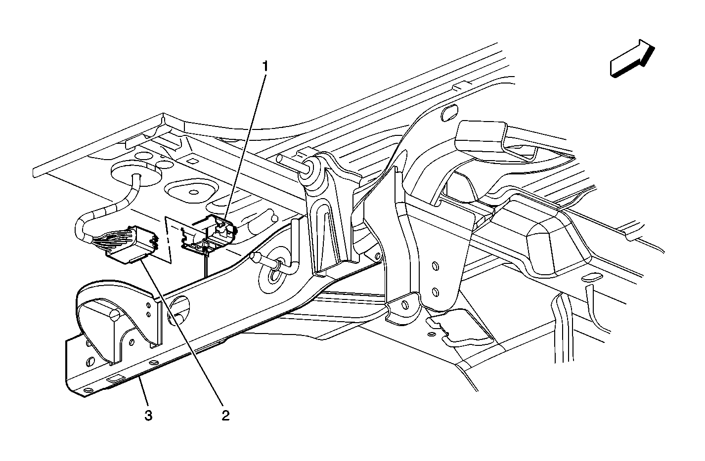
| Figure 26: |
Real Time Damping Connector to Body Wiring Harness
|
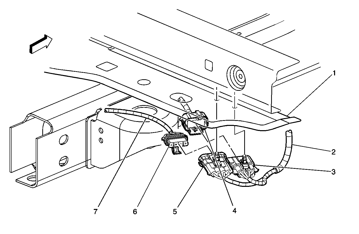
| Figure 27: |
RR Frame -- Lighting Components
|
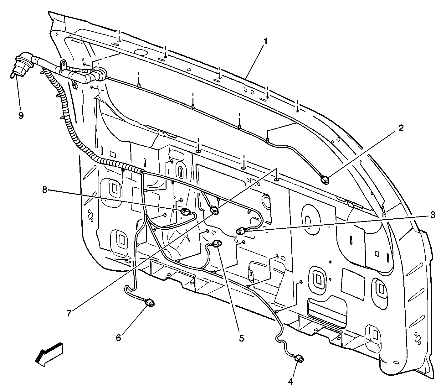
| Figure 28: |
Liftgate Wiring Harness to Liftgate
|