Tools Required
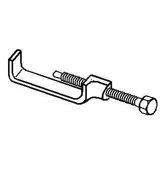
J 36202 Torsion Bar Unloading/Loading Tool.
Removal Procedure
- Raise and support the vehicle. Refer to Lifting and Jacking the Vehicle in General Information.
- Mark the adjustment bolt setting.
- Install J 36202 to the adjustment arm and the crossmember .
- Increase the tension on the adjustment arm until the load is removed from the adjustment bolt and the adjuster nut.
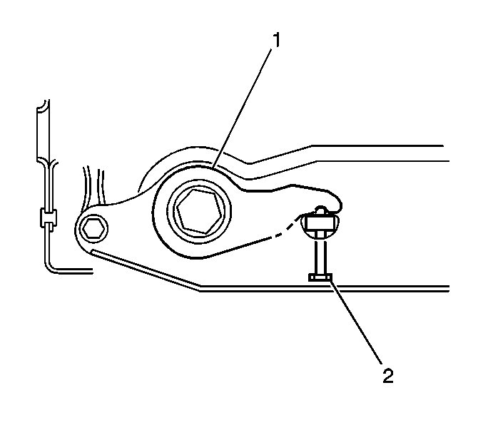
- Remove the adjustment bolt (3) and the adjuster nut (4) (15 Series).
- Remove the adjustment bolt (3) and the adjuster nut (4) (25 Series).
- Remove the J 36202 , allowing the torsion bar to unload.
- Remove the adjustment arm by sliding the torsion bar forward until the torsion bar clears the adjustment arm. Use your hand to support the adjustment arm as the adjustment arm releases from the torsion bar.
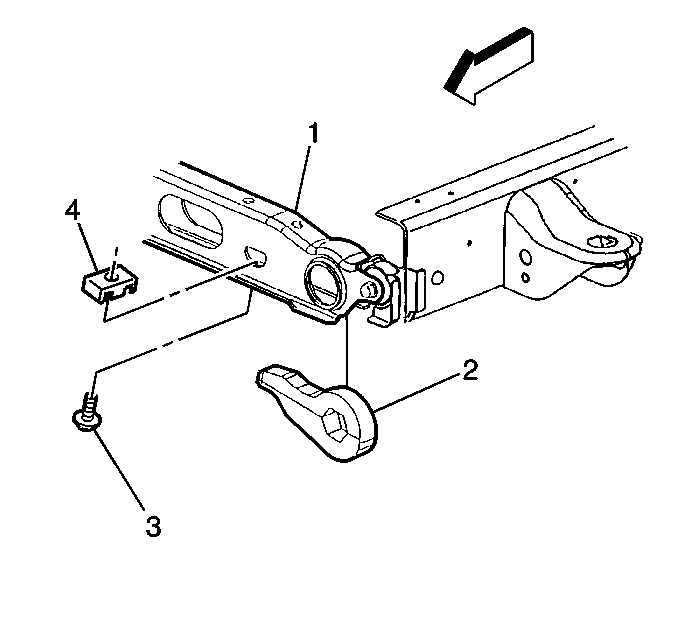
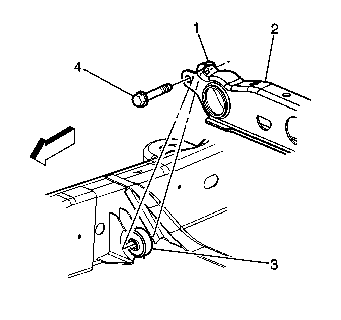
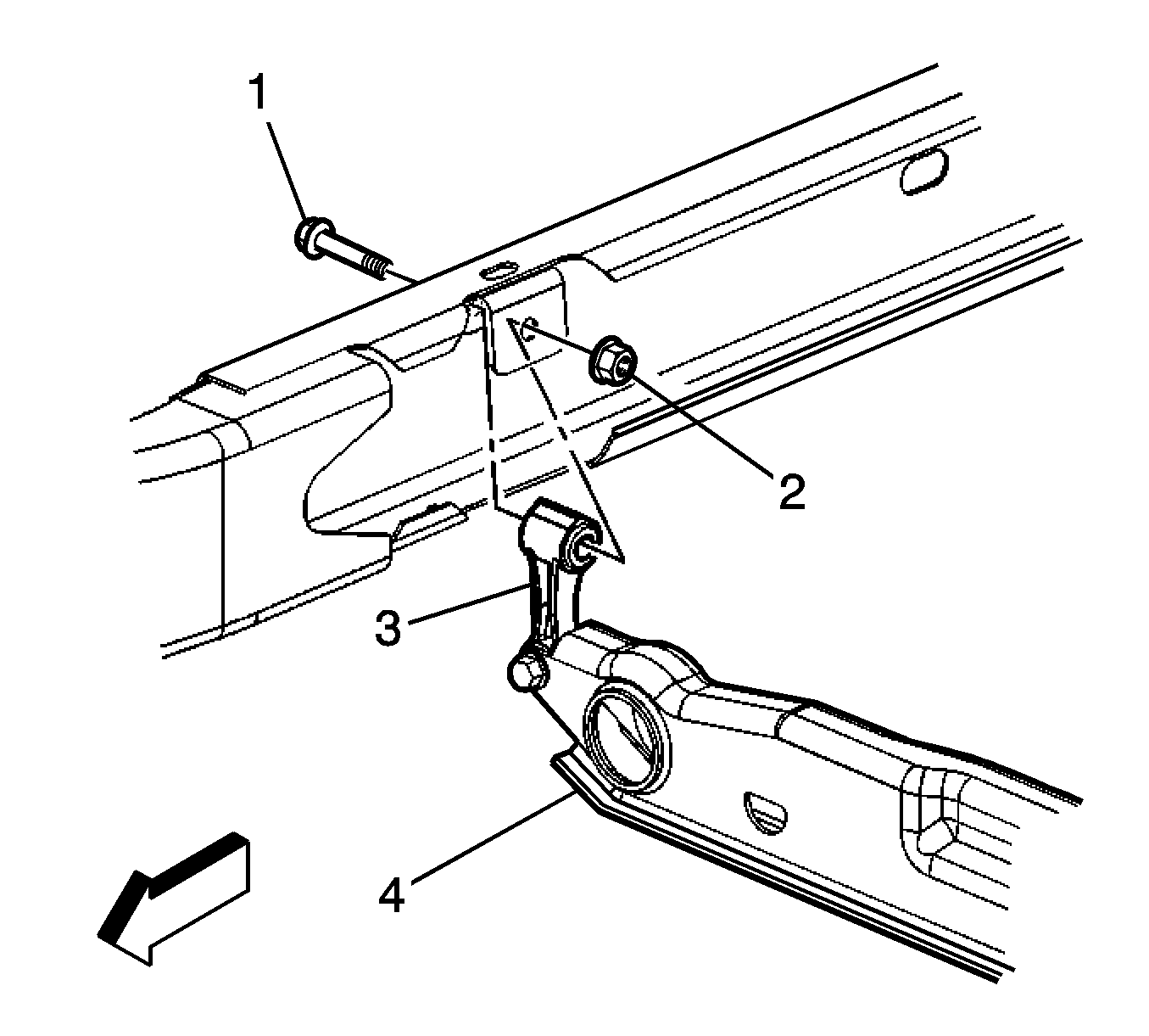
- Remove the torsion bar crossmember bolts (4) from the weld nuts (1) (15 Series).
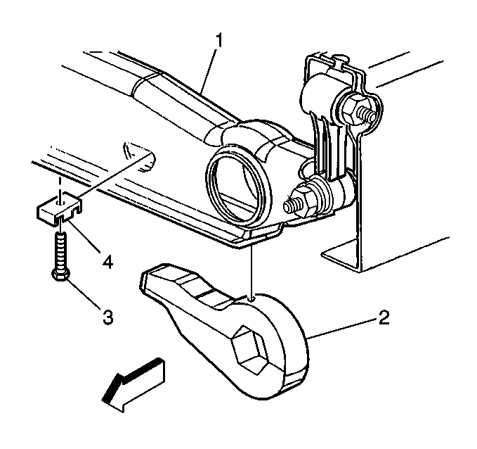
- Remove the upper link mounting nuts (1) and the bolts (2) (25 Series).
- Remove the torsion bar crossmember.
- Remove the torsion bars.
Important: This procedure requires the removal of both torsion bars.

Important: Note the position of the torsion bars as the left and right bars are different.
Installation Procedure
- Install the torsion bars.
- Install the torsion bar crossmember .
- Install the torsion bar crossmember bolts (1) to the weld nuts (4) (15 Series).
- Install the upper link mounting nuts (2) and the bolts (1) (25 Series).
- While supporting the adjustment arm, slide the torsion bar rearward until the torsion bar fully engages the adjustment arm.
- Install the J 36202 to the adjustment arm and the crossmember.
- Increase the tension on the adjustment arm in order to load the torsion bar.
- Install the adjustment bolt (3) and the adjuster nut (4) (15 Series).
- Install the adjustment bolt (3) and the adjuster nut (4) (25 Series).
- Remove the J 36202 releasing the tension on the torsion bar until the load is taken up by the adjustment bolt.
- Remove the safety stands.
- Lower the vehicle.
- Measure the Z height. Refer to Wheel Alignment Specifications in Wheel Alignment.
- Turn the adjustment bolt (2) clockwise to increase the Z height and counter clockwise to decrease the Z height.
Notice: Use the correct fastener in the correct location. Replacement fasteners must be the correct part number for that application. Fasteners requiring replacement or fasteners requiring the use of thread locking compound or sealant are identified in the service procedure. Do not use paints, lubricants, or corrosion inhibitors on fasteners or fastener joint surfaces unless specified. These coatings affect fastener torque and joint clamping force and may damage the fastener. Use the correct tightening sequence and specifications when installing fasteners in order to avoid damage to parts and systems.
Tighten
Tighten the bolt to 95 N·m (70 lb ft).
Tighten
Tighten the nut to 95 N·m (70 lb ft).