Removal Procedure
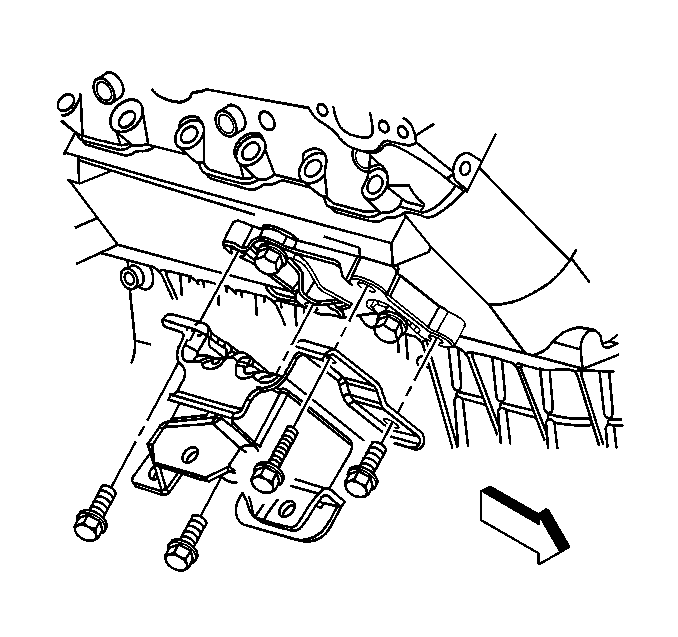
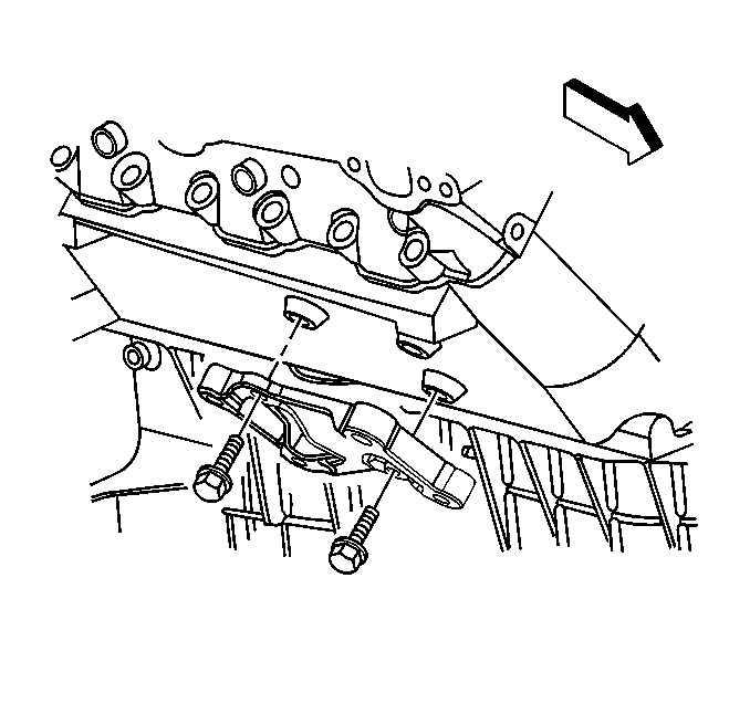
- From under the hood, remove the three bolts holding the engine mount to the engine mount frame bracket.
- Raise the vehicle. Refer to Lifting and Jacking the Vehicle in General Information.
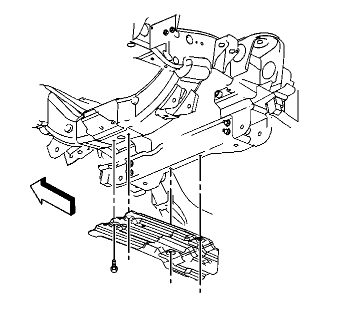
- Remove the oil pan skid plate.
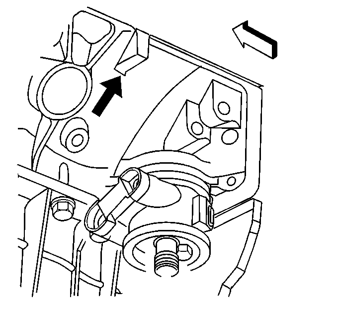
- Using a jack on the square tab (left side shown) at the rear of the engine block, raise the engine.
- In order to access the square tab on the right side of the engine, remove the starter. Refer to Starter Motor Replacement in Engine Electrical.
- Remove the bolts holding the engine mount to the engine mount bracket and the engine.
- Remove the engine mount.
- Remove the engine mount bracket to the engine, if necessary.
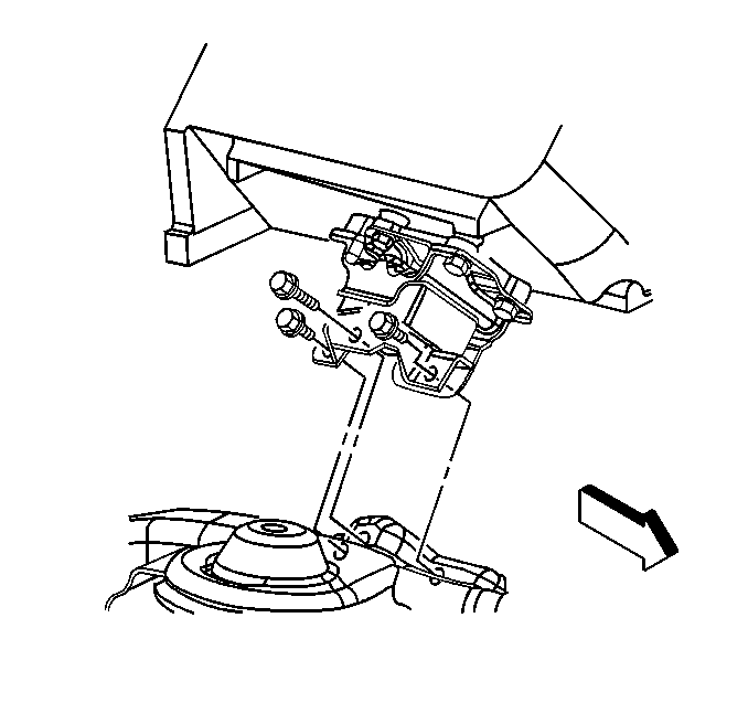
- In order to replace the engine mount frame bracket, remove the two through-bolts.
- Remove the engine mount frame bracket.
Notice: Broken or deteriorated mounts can cause misalignment and destruction of certain drive train components. When a single mount breaks, the remaining mounts are subjected to abnormally high stresses.
Notice: When raising or supporting the engine for any reason, do not use a jack under the oil pan, any sheet metal, or the crankshaft pulley. Lifting the engine in an unapproved manner may cause component damage.
Installation Procedure
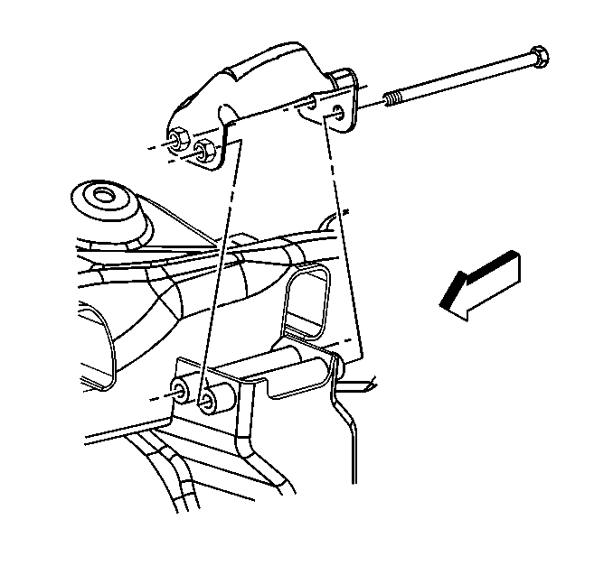
- Position the engine mount frame bracket on the frame.
- Install the two through-bolts.
- Install the engine mount bracket to the engine, if removed.
- Install the bolts holding the engine mount bracket to the engine.
- Install the engine mount.
- Install the long bolt holding the engine mount and the engine mount bracket to the engine.
- Install the three bolts holding the engine mount to the engine mount bracket.
- Lower the engine.
- Install the starter, if removed. Refer to Starter Motor Replacement in Engine Electrical.
- Install the oil pan skid plate.
- Lower the vehicle.
- Install the three bolts holding the engine mount to the engine mount frame bracket.
Notice: Use the correct fastener in the correct location. Replacement fasteners must be the correct part number for that application. Fasteners requiring replacement or fasteners requiring the use of thread locking compound or sealant are identified in the service procedure. Do not use paints, lubricants, or corrosion inhibitors on fasteners or fastener joint surfaces unless specified. These coatings affect fastener torque and joint clamping force and may damage the fastener. Use the correct tightening sequence and specifications when installing fasteners in order to avoid damage to parts and systems.
Tighten
Tighten the through-bolts to 75 N·m (55 lb ft).
Tighten
Tighten the engine mount bracket bolts to 50 N·m (37 lb ft).
Tighten
Tighten the bolts to 50 N·m (37 lb ft).
Tighten
Tighten the bolts to 20 N·m (15 lb ft).
Tighten
Tighten the engine mount to engine mount frame bracket bolts to 65 N·m
(50 lb ft).
