Removal Procedure
- Remove the engine sight shield, if required. Refer to Upper Intake Manifold Sight Shield Replacement .
- Remove the connector position assurance (CPA) lock.
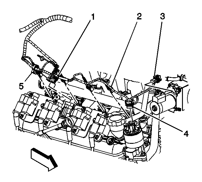
- Disconnect the main electrical connector (1) to the ignition coil wire harness.
- Remove the harness clips (2).
- Reposition the engine harness, if necessary.
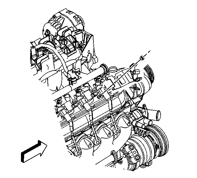
- Remove the spark plug wires from the ignition coils.
- Reposition the surge tank/heater hoses from the heater hose bracket.
- Remove the heater hose bracket nut and bracket.
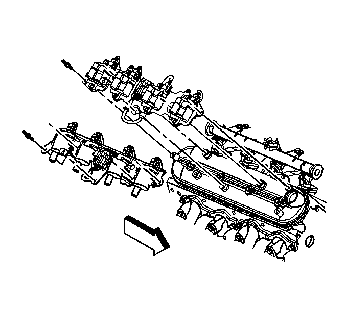
- Remove the ignition coil bracket studs.
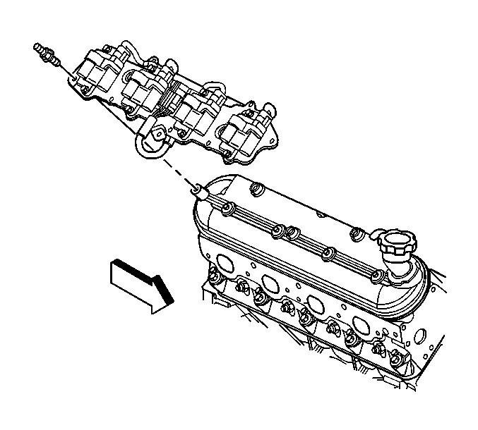
- Remove the ignition coil bracket.
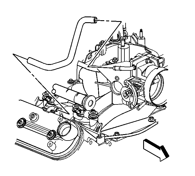
- Remove the positive crankcase ventilation (PCV) hose.
- Loosen the valve rocker arm cover bolts.
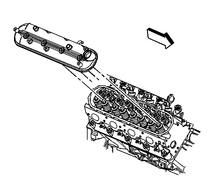
- Remove the valve rocker arm cover.
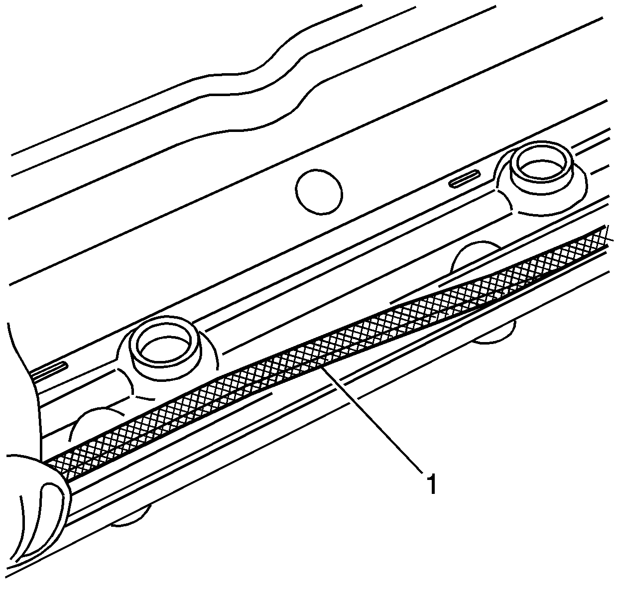
- Remove and discard the old gasket (1).
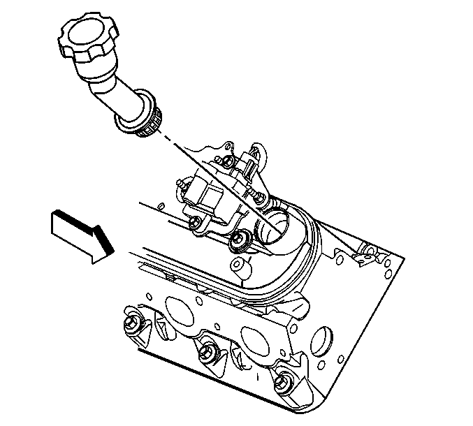
- Remove the oil fill tube from the rocker cover, if required.
- If required, clean and inspect the rocker arm cover. Refer to Valve Rocker Arm Cover Cleaning and Inspection .
| • | Twist each plug wire 1/2 turn. |
| • | Pull only on the boot in order to remove the wire from the ignition coil. |
Installation Procedure
Important:
• All gasket surfaces should be free of oil or other foreign material during
assembly. • DO NOT reuse the valve rocker arm cover gasket. • If the oil fill tube has been removed from the rocker arm cover, install
a NEW fill tube during assembly.
- Lubricate the O-ring seal of the NEW oil fill tube with clean engine oil.
- Insert the NEW oil fill tube into the rocker arm cover.
- Install the oil fill cap into the tube.
- Install a NEW rocker cover gasket (1) into the valve rocker arm cover lip.
- Install the valve rocker arm cover.
- Tighten the rocker arm cover bolts.
- Install the PCV hose.
- Apply threadlock GM P/N 12345382 (Canadian P/N 10953489), or equivalent to the threads of the bracket bolts.
- Install the ignition coil bracket.
- Install the ignition coil bracket studs.
- Install the heater hose bracket and nut.
- Position the surge tank/heater hoses to the heater hose bracket.
- Install the spark plug wires to the ignition coils.
- Position the engine harness, if necessary.
- Install the harness clips (2).
- Connect the main electrical connector (1) feeding the ignition coils.
- Install the CPA lock.
- Install the engine sight shield, if required. Refer to Upper Intake Manifold Sight Shield Replacement .

Rotate the tube clockwise until locked in the proper position.
Rotate the cap clockwise until locked in the proper position.


Notice: Use the correct fastener in the correct location. Replacement fasteners must be the correct part number for that application. Fasteners requiring replacement or fasteners requiring the use of thread locking compound or sealant are identified in the service procedure. Do not use paints, lubricants, or corrosion inhibitors on fasteners or fastener joint surfaces unless specified. These coatings affect fastener torque and joint clamping force and may damage the fastener. Use the correct tightening sequence and specifications when installing fasteners in order to avoid damage to parts and systems.
Tighten
Tighten the bolts to 12 N·m (106 lb in).

Tighten
Tighten the studs to 12 N·m (106 lb in).

Tighten
Tighten the nut to 9 N·m (80 lb in).

