Engine Coolant Loss with No Visible Leaks (Reseal Injector Sleeve)

| Subject: | Engine Coolant Loss with No Visible Leaks (Reseal Injector Sleeve) |
| Models: | 2001-2004 Chevrolet Silverado |
| 2001-2004 GMC Sierra |
| 2003-2004 Chevrolet and GMC C4500/5500 Models |
| with 6.6L Diesel Engine (VIN1 - RPO LB7) |
This bulletin is being revised to add technician cautions. Please discard Corporate Bulletin Number 03-06-02-005A (Section 06-Engine).
Condition
Some owners may comment on engine coolant loss with no visible leaks. Excessive white smoke or a coolant type odor coming from the exhaust pipe, along with low coolant levels, may indicate coolant in the combustion chamber.
Cause
Condition may be caused by engine coolant entering the cylinder due to a dirty or damaged seal between the fuel injector sleeve and the cylinder head.
Correction
Perform the following diagnosis to determine the cause of the coolant loss.
- External/Internal Coolant Leaks:
- Cooling System Pressurization:
- Cylinder Leakage Test:
- Inspection and Repair:
| 1.1. | Verify that there are no external coolant leaks. Refer to the Loss of Coolant procedure in the Engine Cooling section of the Service Manual. |
| 1.2. | If the vehicle is equipped with an Exhaust Gas Recirculation (EGR) system, inspect the EGR valve and intake system for evidence of internal coolant leakage. Replace the EGR cooler if any condition is found. Refer to Exhaust Gas Recirculation (EGR) Valve Cooler Tube Replacement procedure in the Engine Controls -- 6.6L sub-section of the Service Manual. |

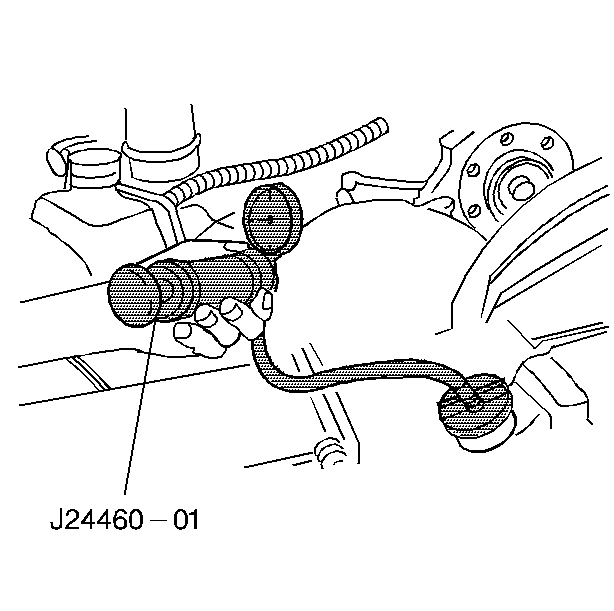
| 2.1. | On a cold engine with the cooling system depressurized, install the J 24460-01 Radiator Pressure Tester. |
| 2.2. | Start the engine and bring it to operating temperature. |
| 2.3. | Shut off the engine. |
| 2.4. | Using the J 24460-01 Radiator Pressure Tester, bring the cooling system pressure to 15 psi (103 kPa). |
| 2.5. | Allow the engine to cool. Observe for a drop in the cooing system pressure. |
| 2.6. | Disable the fuel system by removing the IGN 1 relay on C/K trucks or the IGN B relay on C4500/5500 trucks using the J 43244 Relay Puller Pliers. |
| 2.7. | Disconnect the 4-wire glow plug control circuit connector from the glow plug relay/controller assembly. |
| 2.8. | Remove the glow plugs. Refer to the Glow Plug Replacement -- Bank 1 and the Glow Plug Replacement -- Bank 2 procedures in the Engine Controls -- 6.6L sub-section of the Service Manual. Inspect for evidence of coolant on the glow plug tips. Note any cylinders that show evidence of coolant leakage. |
| Caution: Keep hands and face clear of glow plug holes while cranking. Hot liquid or gases may be expelled during cranking. |
| 2.9. | Place white paper in front of all the glow plug holes and crank the engine over for two compression strokes. |
| 2.10. | Inspect the paper for evidence of coolant and note the appropriate cylinders. |
| 2.11. | Release the pressure from the cooling system and remove the J 24460-01 Radiator Pressure Tester. |
| 3.1. | Rotate the engine to bring the cylinder to be tested to Top Dead Center. |

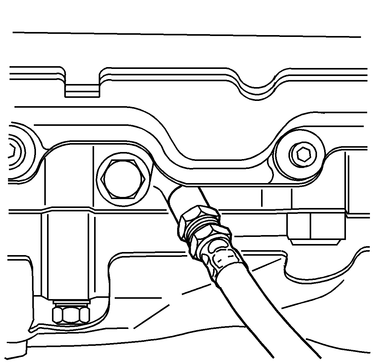
| 3.2. | Install the J 35667-9 Cylinder Head Leakdown Adapter and the J 35667-A Cylinder Head Leakdown Tester to the cylinder. |
| 3.3. | Apply shop air to the J 3566-7 Cylinder Head Leakdown Tester and adjust according to the manufacturer's instructions. |
| 3.4. | Inspect for excessive cylinder leakage and air bubbles in the cooling system. |
| 3.5. | Repeat steps 3.1 through 3.4 for each cylinder. Note any cylinders that indicate leakage. |
| 4.1. | Remove the fuel injector sleeves of the cylinders that show evidence of coolant leakage. Refer to the Fuel Injector Sleeve Replacement procedure in the Engine Mechanical -- 6.6L sub-section of the Service Manual. |
| 4.2. | Inspect the inside of the fuel injector sleeve for damage to the fuel injector sealing surface. Damage to this portion of the fuel injector sleeve may indicate a loose injector caused by improper tightening or a missing copper washer. A loose injector will allow the fuel injector and the fuel injector sleeve to bounce inside the cylinder head, resulting in coolant leakage to the cylinder. If damage is found, replace the affected components. |

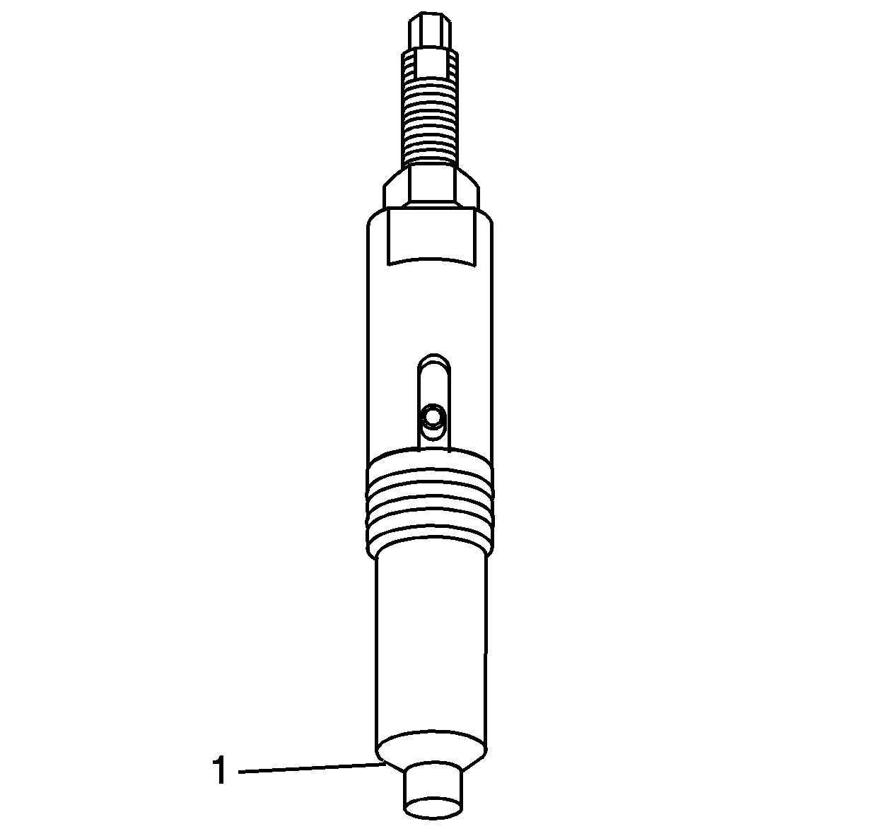
| 4.3. | Inspect the tapered sealing surface of the cylinder head and the fuel injector sleeve (1) for evidence of machining debris, carbon tracking, improper machining or damage. If improper machining or damage is found, replace the affected component. If there is machining debris found on the fuel injector sleeve or cylinder head sealing surfaces, clean the debris and reinstall the fuel injector sleeve. Refer to Fuel Injector Sleeve Replacement in the Engine Mechanical -- 6.6L sub-section of the Service Manual. |
| 4.4. | If no debris or damage is found on the fuel injector sleeve or the fuel injector sleeve bore in the cylinder head, remove the cylinder head and inspect the cylinder head and gasket for damage. Replace components as necessary. |
Warranty Information
For vehicles repaired under warranty, use:
Labor Operation | Description | Labor Time |
|---|---|---|
J0497 | Sleeve, Fuel Injector - Right Bank - Replace | 3.4 hrs |
Add: | To Replace Each | 0.1 hr |
Add: | To Replace All | 0.3 hr |
J0498 | Sleeve, Fuel Injector - Left Bank - Replace | 4.4 hrs |
Add: | To Replace Each | 0.1 hr |
Add: | To Replace All | 0.3 hr |
J0499 | Sleeve, Fuel Injector - Both Banks - Replace | 7.5 hrs |
Add: | To Replace Each | 0.1 hr |
Add: | To Replace All - Both Banks | 0.6 hr |
