Engine Overheats or Runs Hot in High Ambient Temperature When Towing or Hauling on Long Inclines (Install 2006 Air Cleaner Assembly)

| Subject: | Engine Overheats or Runs Hot in High Ambient Temperature When Towing or Hauling on Long Inclines (Install 2006 Air Cleaner Assembly) |
| Models: | 2004-2005 Chevrolet Silverado 2500/3500 Series |
| 2004-2005 GMC Sierra 2500/3500 Series |
| with 6.6L Diesel Engine (VIN 2 -- RPO LLY) |
| Built From January 1, 2004 Through 2005 End of Production |
This bulletin is being revised to clarify steps 10 and 11 and the illustration in step 10 of the procedure. Please discard Corporate Bulletin Number 06-06-04-036C (Section 06 -- Engine/Propulsion System).
Condition
Some customers may comment that while towing a trailer, or if the vehicle is loaded on a long upgrade climb and high ambient temperatures, the Driver Information Center states Engine Coolant Hot, the engine overheats and there is a loss of power and air conditioning.
Cause
This condition may be caused by any of the following possibilities:
| • | Installation of an aftermarket grille. |
| • | A plugged charge air cooler. |
| • | Fan clutch not operating properly. |
| • | Drive belt slip. |
| • | An overfilled transmission. |
| • | Turbocharger not operating properly. |
| • | A plugged air filter. |
Correction
Inspect the following areas FIRST.
| • | Inspect for changes to the air intake area or for aftermarket grille accessories. Make sure all air dams are in place and not modified. Remove any aftermarket grille or accessories that may restrict air flow. |
| • | Visually inspect the Charge Air Cooler (CAC) to insure that it is not plugged externally. Use the Special Tool J 46091 to ensure that all pipe connections are properly sealed and the CAC does not have a leak. |
| • | Monitor the fan clutch operation and complete SI Diagnostics for Fan Clutch Diagnosis. If the fan seems to be cycling on and off when the engine RPMs are above 2800, this could indicate a belt slip condition. |
| • | Monitor the actual and desired turbo vane position to verify that the turbocharger is performing properly. |
| • | Inspect the transmission fluid level. An overfilled transmission can add to heat levels in the cooling system. |
| • | Inspect the air induction system. Ensure that the filter is in good condition and is properly installed. |
If no issues were found after the above inspections, install a 2006 air cleaner system using the following procedure.
- Disconnect the mass air flow sensor electrical connector and remove the sensor from the air outlet duct.
- Loosen the clamps and remove the air cleaner outlet duct.
- Remove the air cleaner assembly. Grasp the air filter assembly and pull up on the assembly in order to disengage the retaining pins from the grommets.
- Remove the five 10 mm bolts and the tray.
- Remove the insulation on the inner right fender.
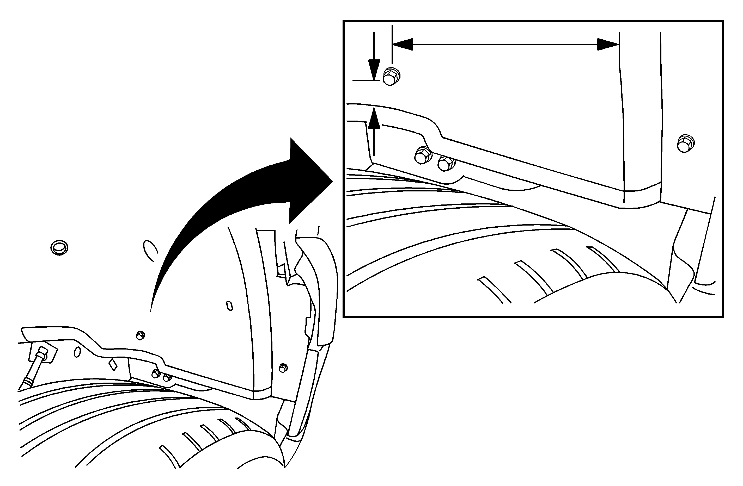
- With the wheel turned to the right, measure from the corner of the wheel liner over 231 mm (9 in) and up 45 mm (1.8 in) as seen in the illustration above.
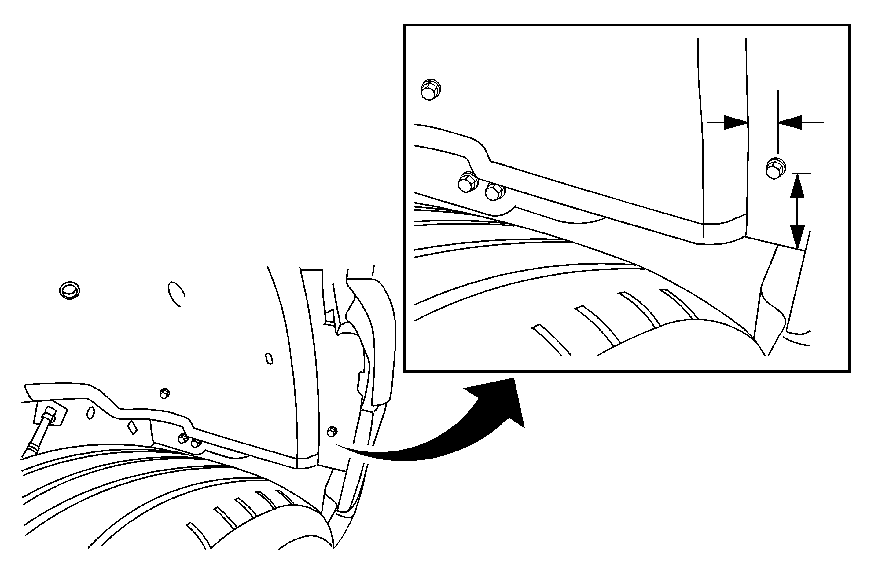
- Measure up 75 mm (3 in) from the bottom of the liner and measure the lip of the liner 20 mm (0.8 in) as seen in the illustration above.
- With a 5/16 or 8 mm drill bit, drill two holes though the wheelhouse liner.
- Remove the wheel liner fasteners and pull the liner back.
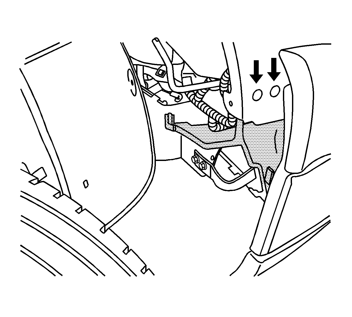
- Install the new baffle assembly intake air (lower baffle) to the fender with the two push-in fasteners. The arrows in the illustration above point to where the push-in fasteners will go.
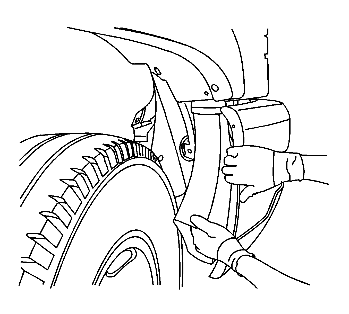
- Install the new inner fender air duct by inserting the duct between the inner and outer sheet metal. The duct has a nipple on the side and will snap in place on the inner sheet metal of the fender.
- Install the wheel liner and fasteners.
- Install the two bolts that retains the baffle assembly intake air to the wheel liner.
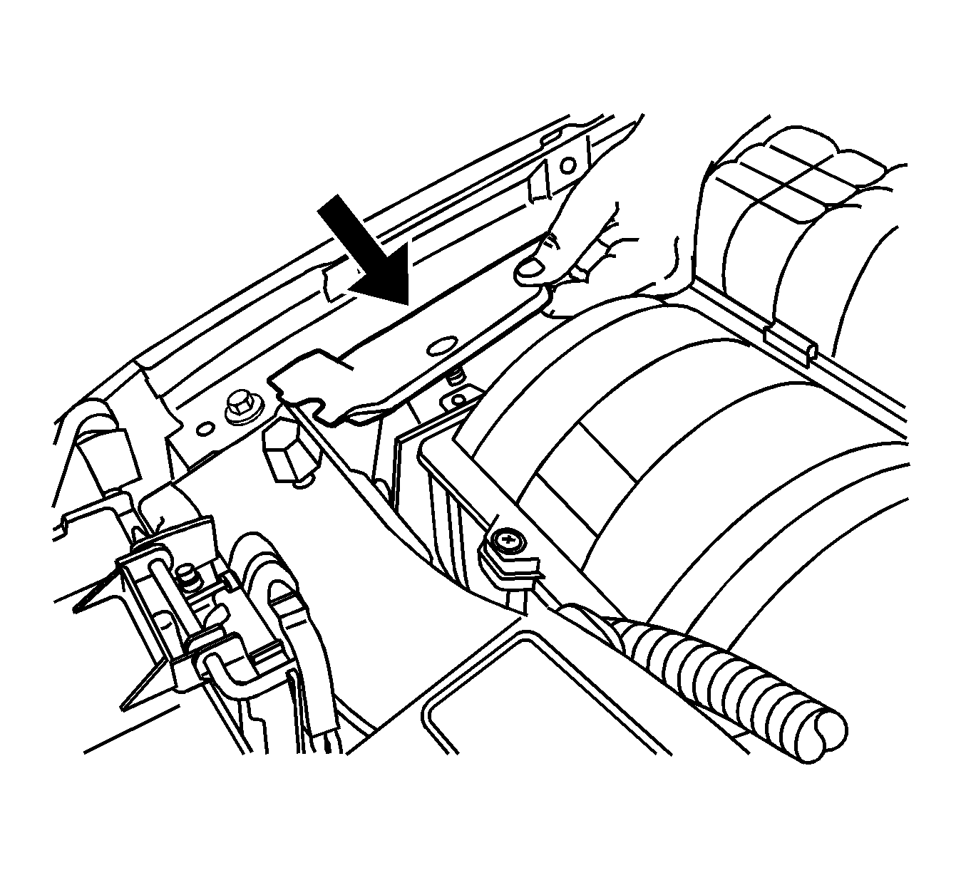
- Install the plastic closeout panel on the radiator support.
- Install the air cleaner bracket, bolts and new tray.
- Install the air cleaner assembly. Push down on the assembly in order to secure it to the bracket.
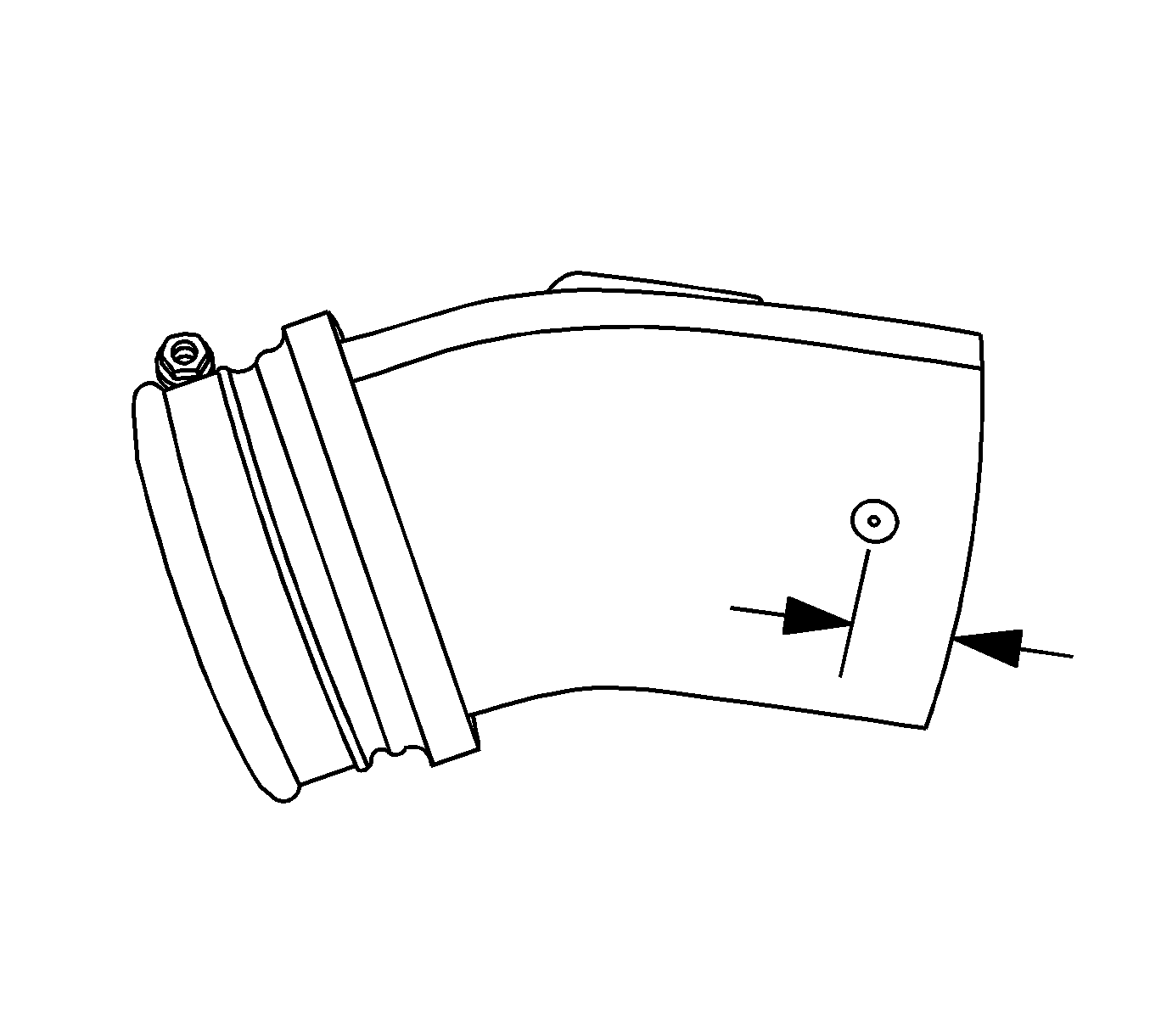
- Measure back from the Caution label on the air cleaner outlet duct 52 mm (2 in) on the existing duct, and cut the duct.
- Measure from the side that was cut, 13 mm (½ in), and drill a 5/32 or 5 mm hole on each side of the duct and install rivets as seen in the illustration above.
- Connect the two ducts together.
- Install the air cleaner outlet duct to the air cleaner assembly and the turbo inlet. It may be necessary to reposition the clamp on the air cooler outlet duct.
- Install the mass air flow sensor and connect the connector.
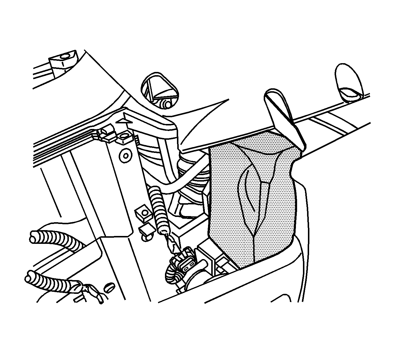
- Install the intake horizontal baffle as seen in the illustration above.
- Remove the right head lamp assembly. Refer to SI if necessary. With the head lamp out, clean the surface with 3M® General Purpose Adhesive Cleaner, or equivalent. Install the baffle intake air (foam block) on the radiator support as seen in the illustration above.
- Reprogram the vehicle PCM with new software. Refer to TIS for the calibration cylindrical air cleaner housing.
- Reposition the engine oil indicator (dipstick) tube toward the fender so it will clear the air cleaner outlet duct.
Tighten
Tighten the bolts to 9 N·m (80 lb in).
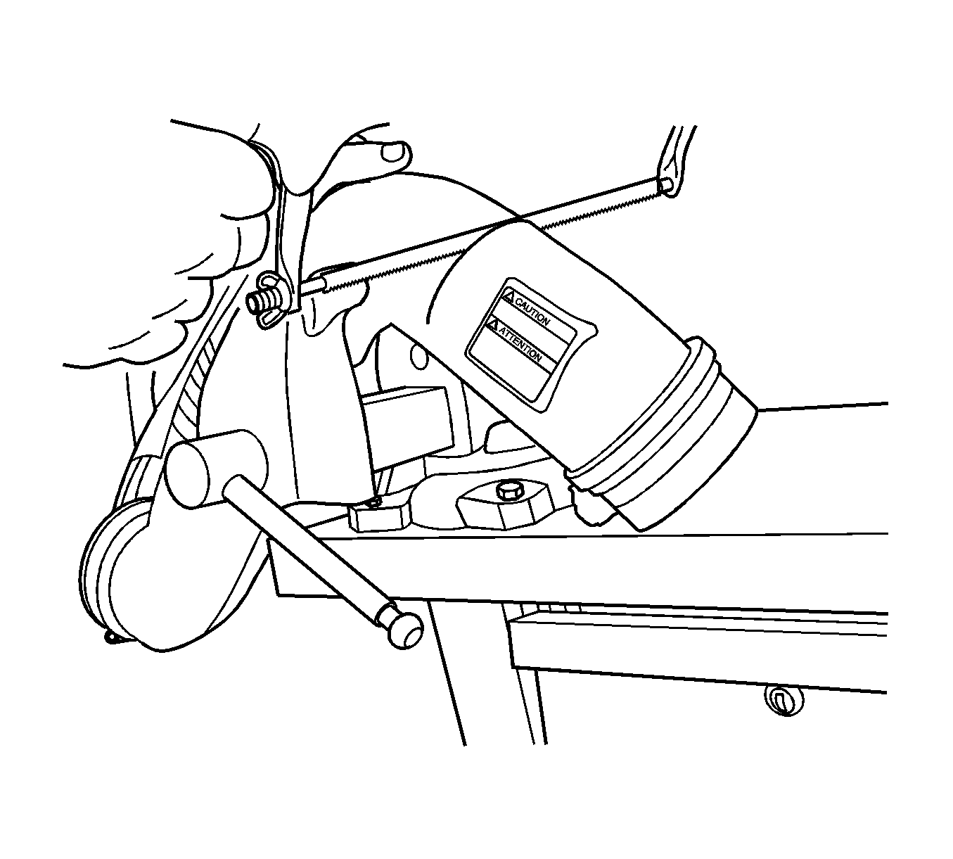
Notice: Do not attempt to cut off the outlet duct on the vehicle or debris could enter the turbo and cause damage.
Tighten
Tighten the three clamps to 4 N·m (35 lb in).
Tighten
Tighten the air cooler outlet duct clamp to 6 N·m (53 lb in).
If the vehicle is a 2004 or 2005 GMC Sierra, the following items will have to be installed to ensure cooler air is entering the system.
- Remove the left and right head lamp assembly. Refer to SI if necessary.
- Install the seal around the lamp with the wide part of the seal across the top of the lamp.
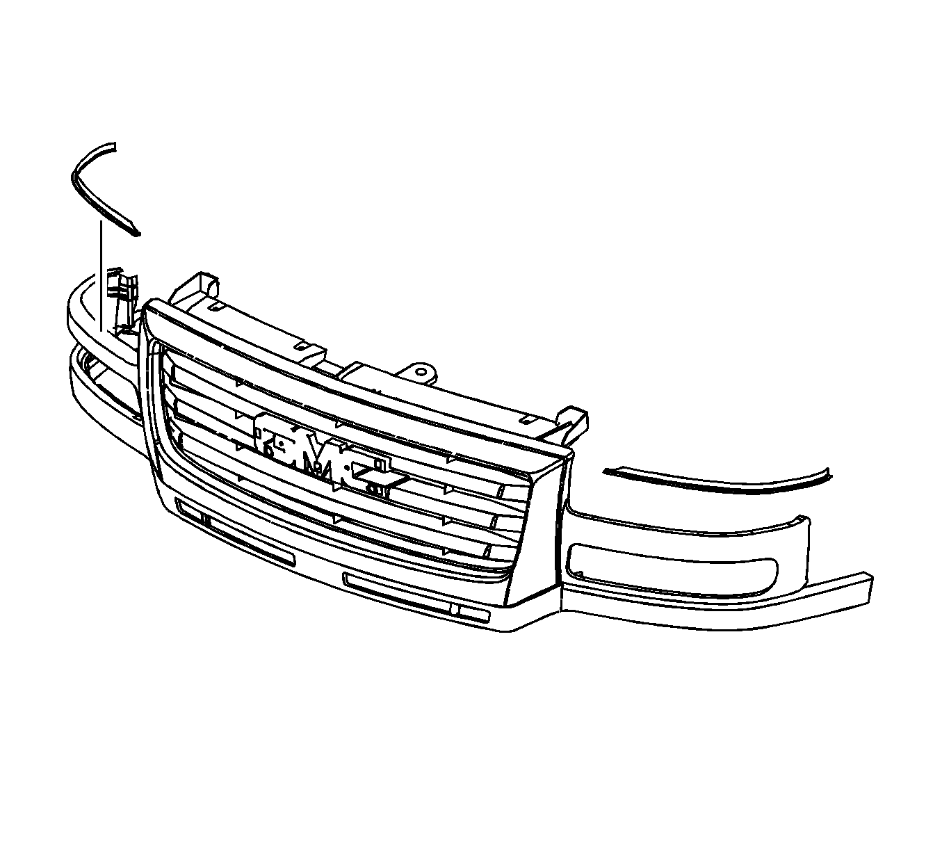
- Remove the grille. Refer to SI if necessary.
- Install the seals on the left and right side of the grille as seen in the illustration above.
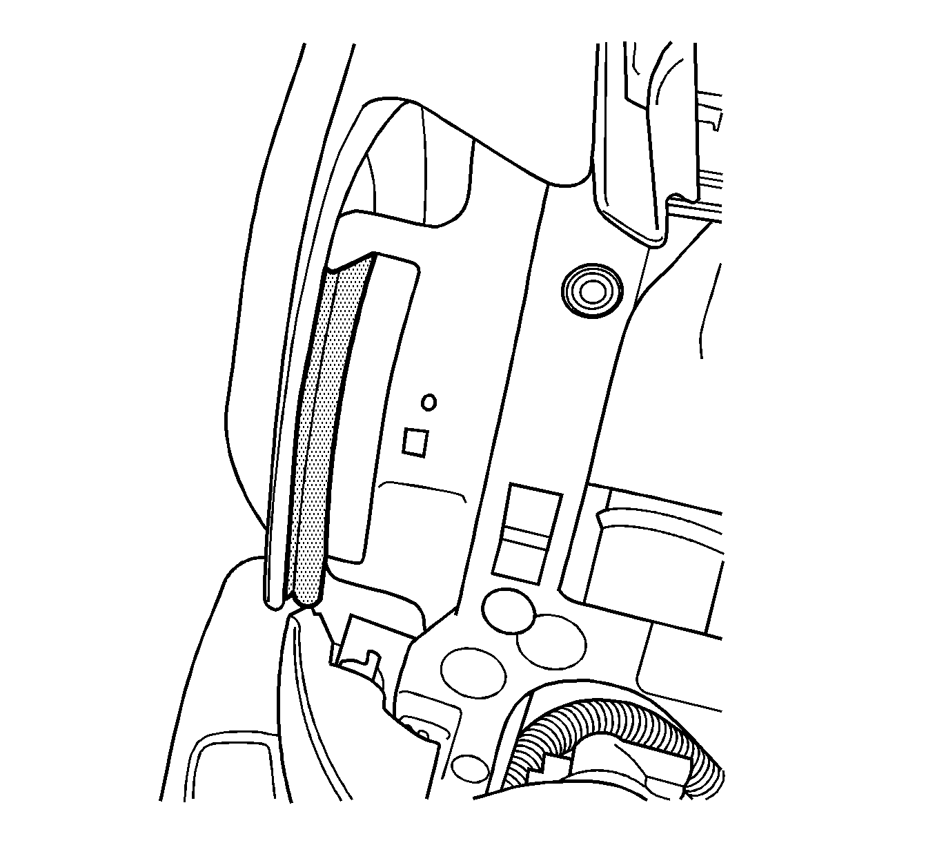
- Clean the surface of the inner right fender and install the vertical seal as seen in the illustration above.
- Clean the lip on the left fender and install the horizontal hood seal to the fender.
- Install the grille.
- Install the head lamps. Refer to SI if necessary.
Important: Ensure that the sealing is optimized between the air cleaner housing and the inner fender.
Parts Information
Part Number | Description | Qty |
|---|---|---|
89060671 | Cleaner Assembly Air | 1 |
15295257 | Bracket (Air Cleaner Support) | 1 |
15837090 | Duct Assembly A/C Cleaner Outlet | 1 |
15258717 | Baffle Assembly Intake Air (Lower Baffle) | 1 |
11610055 | Bolt Intake Air Baffle (Lower Baffle) | 2 |
11561878 | Retainer | 2 |
15834077 | Baffle Assembly Intake Air Horizontal | 1 |
15801087 | Baffle Intake Air Vertical | 1 |
15830245 | Baffle Intake Air (Foam Block ) | 1 |
15197202 | Duct Lower Intake Air Fender Duct (Chevrolet Only) | 1 |
9442974 | Rivet | 2 |
15180834 | Duct Lower Intake Air Fender Duct (GMC Only) | 1 |
15853969 | Seal Strip F/FDR (GMC Only) | 1 |
15853968 | Seal Strip Fender (GMC Only) | 1 |
19122411 | Seal Head Lamp Left (GMC Only) | 1 |
19122412 | Seal Head Lamp Right (GMC Only) | 1 |
15839771 | Molding-RAD GRL Seal Lower Head Lamp/Grille Left (GMC Only) | 1 |
15839771 | Molding-RAD GRL Seal Lower Head Lamp/Grille Right (GMC Only) | 1 |
15762819 | Strip-F/Fdr Bond Left (GMC Only) | 1 |
Warranty Information
For vehicles repaired under warranty, use:
Labor Operation | Description | Labor Time |
|---|---|---|
J7910* | Air Cleaner System (Chevrolet) | 1.2 hrs |
J7912* | Air Cleaner System (GMC) | 1.4 hrs |
*This labor operation number is for bulletin use only. This number will not be published in the Labor Time Guide. | ||
