RATTLE IN INSTRUMENT CLUSTER UNABLE TO SEE FUEL/TEMP GAGES

SUBJECT: RATTLE IN INSTRUMENT CLUSTER, UNABLE TO SEE FUEL/TEMPERATURE GAGES
MODEL and YEAR: 1987-91 G VANS
THIS BULLETIN CANCELS AND SUPERSEDES DEALER SERVICE BULLETIN NO. 9l-5l2-8C, DATED SEPT. 1992. THE SERVICE PROCEDURE AND PARTS SECTION HAS BEEN CHANGED. ALL COPIES OF 9l-5l2-8C SHOULD BE DISCARDED.
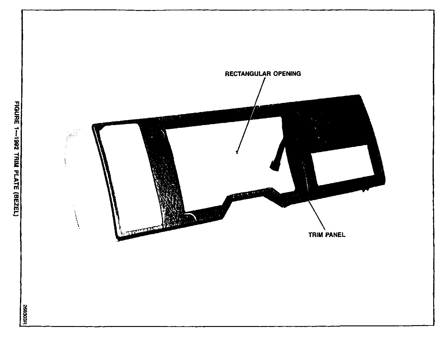
Some owners of 1987-91 G-Vans may comment on a rattle in the instrument cluster or more specifically the odometer reset rod hitting the instrument cluster lens. In addition, some owners may comment on not being able to clearly and easily see the fuel and temperature gages. The above conditions may be corrected by replacing the Trim Panel (bezel), Cluster Retainer, and Lens with a 1992 Trim Panel (bezel), Cluster Retainer, and Lens. The new Trim Panel shown in (Figure 1) is distinguished by its large retangular opening as compared to prior years tunnel openings. The new lens is distinguished by its concave rectangular shape. The new retainer has directional arrows upper center positioned for the turn signal indicators. Also, the new retainer no longer uses a metal upper mounting bracket.
SERVICE PROCEDURE:
Removal of the Cluster and Trim Panel (Bezel)
NOTE: In the following procedure the transmission shift lever will have to be maneuvered as necessary to provide clearance to the screws.
1. Block the vehicle's wheels.
2. Disconnect the negative battery cable.
3. Tilt the steering column fully down, if possible.
4. Remove the Trim Panel (Bezel) as follows:
*Remove the rear A/C and heater control knobs, if applicable, by placing each knob in the OFF position and pulling it from its shaft.
*Remove six screws, three across the top front and three at the bottom of the panel.
*Lift off the panel.
5. Remove the Cluster.
*Remove the two 10 mm screws at the lower corners of the cluster.
*Disconnect the speedometer cable, if applicable.
*Pull the cluster forward and disconnect the wiring connector on the back of the cluster.
6. Removal of the Old Case Retainer, Bracket, Lens.
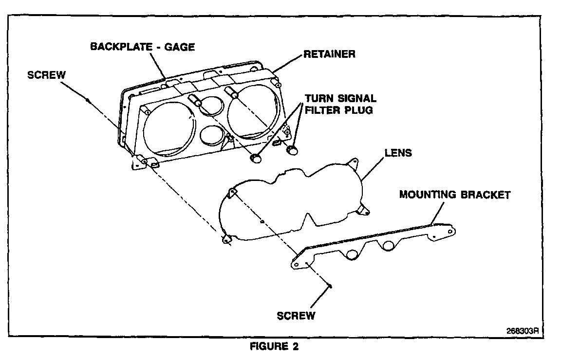
*Position the cluster with the lens face down and remove the (5) six-point torx screws from the backplate of the cluster, and remove the retainer (Figure 2).
*Remove the two upper screws that hold the mounting bracket to the retainer, and the two lower screws that hold the lens to the front of the retainer case and discard the lens and the bracket.
*Remove the two turn signal filter plugs from the retainer case and save, discard the retainer case.
Installation of the New Case Retainer, Lens, and Trim Panel
1. Case Retainer Installation
*Install the two turn signal plugs into the two upper holes of the cluster on either side of the fuel gauge (Figure 3).
*Install the new case retainer p/n 16160907, turn the case so that the gauges are face down, and install the (5) six point torx screws into the backplate of the cluster.
*Turn the case over and insert the lower tabs of the new lens p/n 16160906 into the lower slots of the case retainer.
*Install two torx screws to secure the lens to the upper portion of the case retainer.
2. Install Cluster.
*Re-connect the speedometer cable, if applicable.
*Position the cluster assembly at the Instrument Panel (IP) opening and install the wiring connector.
*Place the cluster in the IP opening and install the two 10 mm screws. Torque the screws to 2.8 N.m (2 lbs.ft.).
3. Trim Plate (Bezel) installation.
*Position the trim plate on the IP and cluster. (See Service Parts Information for the correct Trim Plate)
*Install the six screws. Torque the screws to 1.4 N.m (1 lbs.ft)
*Install the rear A/C and heater control knobs by placing the knobs in the OFF position and pushing them onto the shaft.
4. Connect the negative battery cable.
5. Remove the wheel blocks.
SERVICE PARTS INFORMATION
Instrument Cluster Parts Description ------------------------ ----------- 16160907 Case Retainer 16160906 Lens
Trim Plate (Bezel) Without A/C Application ------------------------------ ----------- 15677324 Gray 15677325 Blue 15677326 Garnet 15677327 Beige 15677313 Black
Trim Plate (Bezel) With A/C Application --------------------------- ----------- 15677329 Gray 15677330 Blue 15677331 Garnet 15677332 Beige 15677334 Black
Parts are currently available from GMSPO.
WARRANTY INFORMATION
For vehicles repaired under warranty use:
Labor Op. Description Labor Time ----------- ----------- ---------- N-4120 Trim Plate Replace 0.4 N-4180 Cluster Assembly Replace 0.6


General Motors bulletins are intended for use by professional technicians, not a "do-it-yourselfer". They are written to inform those technicians of conditions that may occur on some vehicles, or to provide information that could assist in the proper service of a vehicle. Properly trained technicians have the equipment, tools, safety instructions and know-how to do a job properly and safely. If a condition is described, do not assume that the bulletin applies to your vehicle, or that your vehicle will have that condition. See a General Motors dealer servicing your brand of General Motors vehicle for information on whether your vehicle may benefit from the information.
