Removal Procedure
Tools Required
J 39083 Glow Plug
Connector Remover/Installer
- Disconnect the negative battery cable. Refer to
Caution: Unless directed otherwise, the ignition and start switch must be in the OFF or LOCK position, and all electrical loads must be OFF before servicing
any electrical component. Disconnect the negative battery cable to prevent an electrical spark should a tool or equipment come in contact with an exposed electrical terminal. Failure to follow these precautions may result in personal injury and/or damage to
the vehicle or its components.
in General Information.
- Remove the engine cover. Refer to Interior Trim.
- Remove the intake manifold. Refer to
Intake Manifold Replacement
.
- Remove the turbocharger assembly. Refer to Turbocharger.
- Remove the valve rocker arm covers. Refer to
Valve Rocker Arm Cover Replacement
.
- Drain the cooling system. Refer to Cooling and Radiator.
- Remove the components as follows for the left cylinder head:
| • | The air conditioning compressor and the bracket. Refer to HVAC. |
| • | The power steering pump with the bracket. Refer to Power Steering
Gear and Pump. |
| • | The oil level indicator tube |
| • | The thermostat/coolant crossover housing and all related hoses |
| • | The wiring harness, electrical connectors and brackets |
- Remove the components as follows for the right cylinder head:
| • | The vacuum pump and mounting bracket |
| • | The wire harness and electrical connectors; move aside |
- Disconnect the wire from the coolant sensor at the cylinder head.
- Remove the glow plug wires and glow plugs. Use the J 39083
to disconnect the glow plug connectors
from the glow plugs on the right hand cylinder head. The connector cannot
be reached with the hand. Do not pull on the glow plug harness wire.
Important: The valve rocker arm assemblies and the pushrods must be marked for
proper assembly.
- Remove the valve rocker arm assemblies and the pushrods. Refer to
Valve Rocker Arm Cover Replacement
.
- Remove the exhaust manifolds. Refer to
Exhaust Manifold Replacement
.
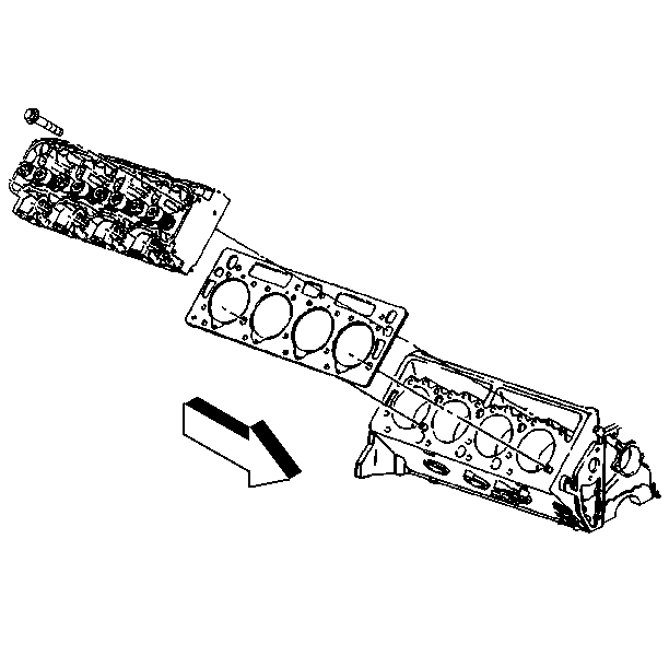
- Remove the cylinder head bolts. The rear bolt in the left cylinder
head may have to remain in the head during removal.

- Remove the left cylinder head.

- Remove the right cylinder head.
- Clean the following parts:
| • | The carbon deposits from the combustion chambers |
| • | Clean all traces of the old head gasket from the cylinder head
and block. The use of a motorized wire brush is not recommended. |
| • | The cylinder head bolt threads using a wire brush |
| • | The metal chips and dirt from the threads in the block |
- Inspect the following components:
| • | The cylinder head for cracks between the intake and exhaust ports.
Use the magnaflux or dye method if available. |
| • | The sealing surfaces of the block and cylinder head for nicks,
heavy scratches or other damage |
| • | The block for missing or damaged dowel pins or dowel pins in the
wrong location |
- Measure the following items:
| • | The cylinder head warpage. |
| • | The pre-chamber installed depth. |
Installation Procedure

Important:
| • | The block gasket surfaces must be clean. |
| • | Do not use a sealer on the head gasket. The head gasket is manufactured
with the proper amount of sealant "printed" on its surface. Additional
sealer may cause leakage or malfunction. In addition, some sealers may attack
the sealant already on the head gasket. |
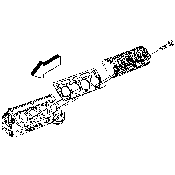
- Install the left head gasket to the block over the dowel pins.
- Connect the rear cylinder head bolt to the cylinder head (left
cylinder head). Due to the clearances, the bolt must be installed at this
time.
- Install the left cylinder head. Make sure the gasket surfaces
are clean. Guide the head carefully in place over the dowel pins.

- Install the right head gasket to the block over the dowel pins.
- Install the right cylinder head. Make sure the gasket surfaces
are clean. Guide the head carefully in place over the dowel pins.

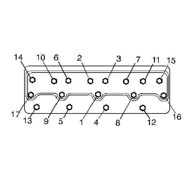
- Install the cylinder head bolts.
| • | Check the cylinder head bolts for stretching |
| • | Make sure the bolt threads are clean |
| • | Apply sealant GM P/N 9985283 or equivalent to the bolt threads
and under the bolt heads |
- Tighten the cylinder heads in the following 3 passes:
Tighten
| • | Bolts to 25 N·m (20 lb ft). |
| • | Bolts to 65 N·m (50 lb ft). |
| • | In sequence, tighten all bolts an additional 90°-100°
(1/4 + turn). |
Notice: Use the correct fastener in the correct location. Replacement fasteners
must be the correct part number for that application. Fasteners requiring
replacement or fasteners requiring the use of thread locking compound or sealant
are identified in the service procedure. Do not use paints, lubricants, or
corrosion inhibitors on fasteners or fastener joint surfaces unless specified.
These coatings affect fastener torque and joint clamping force and may damage
the fastener. Use the correct tightening sequence and specifications when
installing fasteners in order to avoid damage to parts and systems.
- Install the exhaust manifold to the cylinder head.
Tighten
- Tighten the exhaust manifold bolts to 54 N·m (40 lb ft).
- Tighten the exhaust manifold nuts and mounting studs to 30 N·m
(22 lb ft).
- Install the turbocharger assembly. Refer to Turbocharger.
- Install the coolant crossover pipe/thermostat assembly and related
hoses. Use new gaskets.
Tighten
Tighten bolts to 42 N·m (31 lb ft).
- Install the pushrods and the valve rocker arm assemblies in their
original locations.
- Install the glow plug wires. Use the J 39083
to connect the glow plug connectors to the glow plugs.
- Connect the wire to the coolant sensor at the cylinder head.
- Install the components as follows for the right cylinder head:
| • | The wiring harness, electrical connectors and brackets |
| • | The bracket at the rear of the cylinder head |
- Install the components as follows for the left cylinder head:
| • | The air conditioning compressor and bracket, if equipped |
| • | The power steering pump with bracket |
| • | The oil level indicator tube |
| • | The upper radiator hose |
- Install the valve rocker arm covers. Refer to
Valve Rocker Arm Cover Replacement
.
- Install the fuel injection lines.
- Install the intake manifold. Refer to
Intake Manifold Replacement
.
- Install the engine cover. Refer to Interior Trim.
- Fill the cooling system with the proper quantity and grade of
coolant. Refer to Cooling and Radiator.
- Connect the negative battery cable.


