Intake Manifold Installation Upper Intake
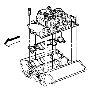
- Install a NEW upper intake manifold gasket into the groove of the intake.
- Install the upper intake manifold. Do not pinch the injector wires between the upper and lower intake manifolds.
- Install the upper intake manifold bolts and studs.
- Tighten the upper intake manifold bolts and studs:
- Tighten the upper intake manifold bolts and studs on the first pass to 5 N·m (44 lb in).
- Tighten the upper intake manifold bolts and studs on the final pass to 10 N·m (88 lb in).
- Install the vacuum hoses.
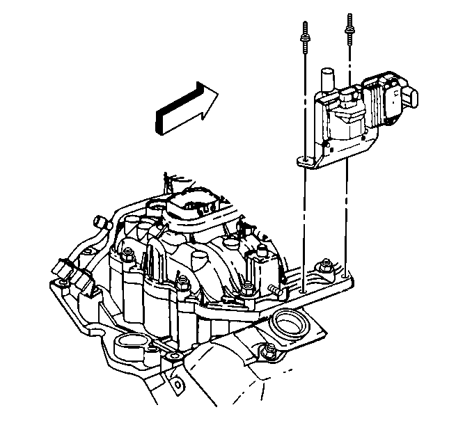
- Install ignition coil and studs.
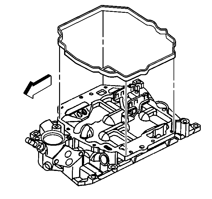
Important: Two stud type bolts installed into the lower intake manifold diagonally opposite from each other will aid in positioning upper intake manifold to the lower intake manifold.
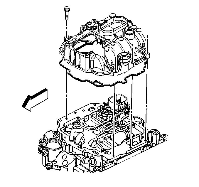
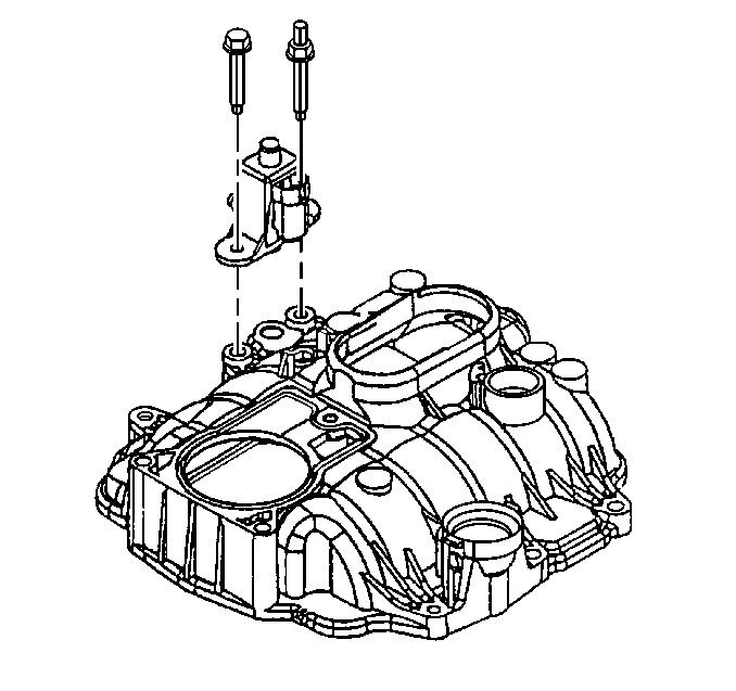
Notice: Use the correct fastener in the correct location. Replacement fasteners must be the correct part number for that application. Fasteners requiring replacement or fasteners requiring the use of thread locking compound or sealant are identified in the service procedure. Do not use paints, lubricants, or corrosion inhibitors on fasteners or fastener joint surfaces unless specified. These coatings affect fastener torque and joint clamping force and may damage the fastener. Use the correct tightening sequence and specifications when installing fasteners in order to avoid damage to parts and systems.
Tighten
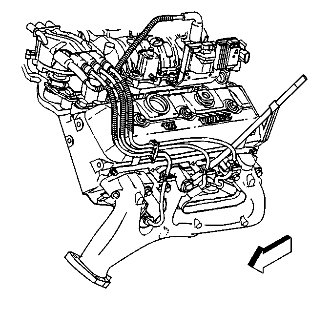
Tighten
Tighten the ignition coil studs to 12 N·m (106 lb in).
Intake Manifold Installation Lower
- Apply sealant to the intake manifold gasket, cylinder head side.
- Install the gaskets onto the cylinder head.
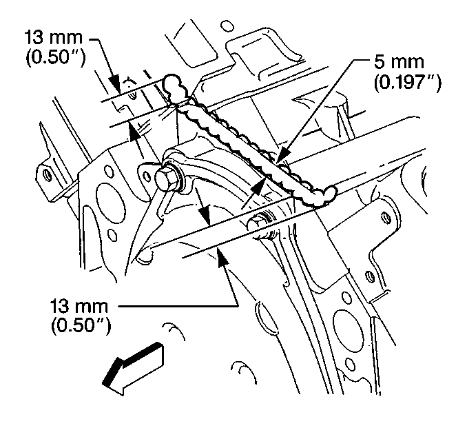
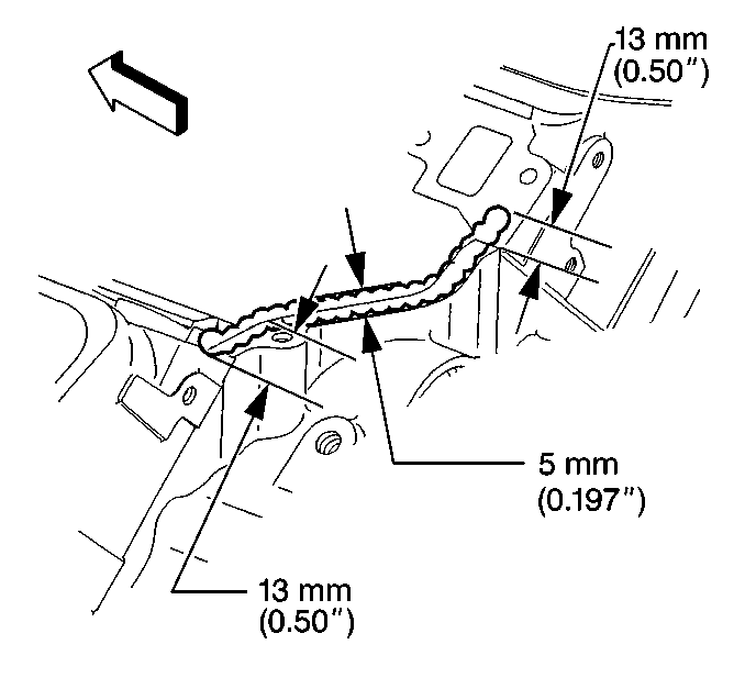
- Apply a 5 mm (0.197 in) bead of the RTV (GM P/N 12346192 or equivalent) to the front of the engine block sealant areas. Extend the RTV bead 13 mm (0.499 in) up the cylinder head in order to seal and retain the gaskets.
- Apply a 5 mm (0.197 in) bead of the RTV (GM P/N 12346192 or equivalent) to the back of the engine block sealant areas. Extend the RTV bead 13 mm (0.499 in) up the cylinder head in order to seal and retain the gaskets.
- Install the lower intake manifold to the engine. Apply sealer GM P/N 12345382 or the equivalent) to the lower intake manifold bolts.
- Install the lower intake manifold bolts.
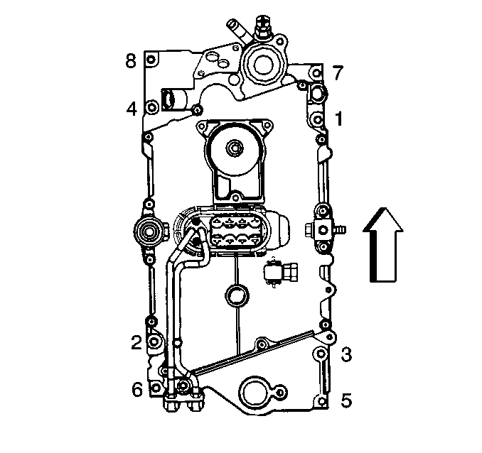
- Use the tightening sequence shown in order to tighten the bolts in three steps.
- Tighten the bolts in the first pass to 3 N·m (27 lb in).
- Tighten the bolts in the second pass to 12 N·m (106 lb in).
- Tighten the bolts in the final pass to 15 N·m (11 lb ft).
- Install oxygen sensor wire support bracket and nut.
- Install EGR inlet tube, clamp, and bolt.
- Install canister purge system tubing.
- Install PCV valve and hose.
Important: Do not reuse intake manifold gaskets. Always install new gaskets.
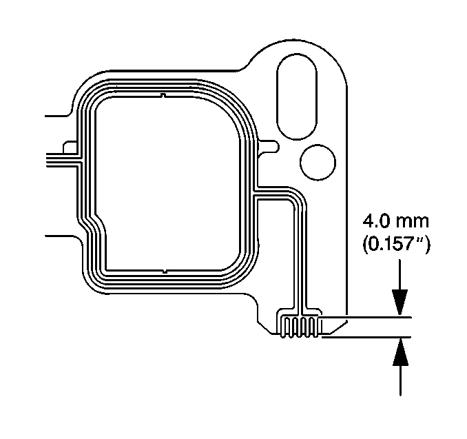
Notice: Apply the proper amount of the sealant when assembling this component. Excessive use of the sealant can prohibit the component from sealing properly. A component that is not sealed properly can leak leading to extensive engine damage.
Tighten
Notice: Use the correct fastener in the correct location. Replacement fasteners must be the correct part number for that application. Fasteners requiring replacement or fasteners requiring the use of thread locking compound or sealant are identified in the service procedure. Do not use paints, lubricants, or corrosion inhibitors on fasteners or fastener joint surfaces unless specified. These coatings affect fastener torque and joint clamping force and may damage the fastener. Use the correct tightening sequence and specifications when installing fasteners in order to avoid damage to parts and systems.
Tighten
Tighten nut to 11 N·m (97 lb in).
Tighten
Tighten bolt to 25 N·m (18 lb ft).
