Assembly Procedure
Refer to the following transmission component locator graphics as needed:

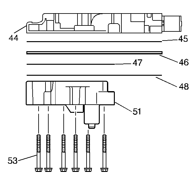
- Install the guide pins into the valve body.
- Install the gasket.
- Install the spacer plate.
- Install the gasket.
- Install the accumulator housing assembly onto the valve body assembly.
- Install the bolts using an 8 mm socket, through the accumulator housing into the valve body assembly.
- Install the guide pins.
Installation Procedure
Refer to the following transmission component locator graphics as needed:


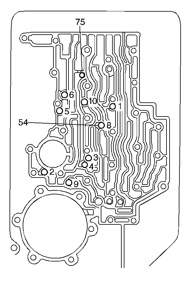
- Install the eight check balls in the proper location into the case fluid passages.
- Install the gasket.
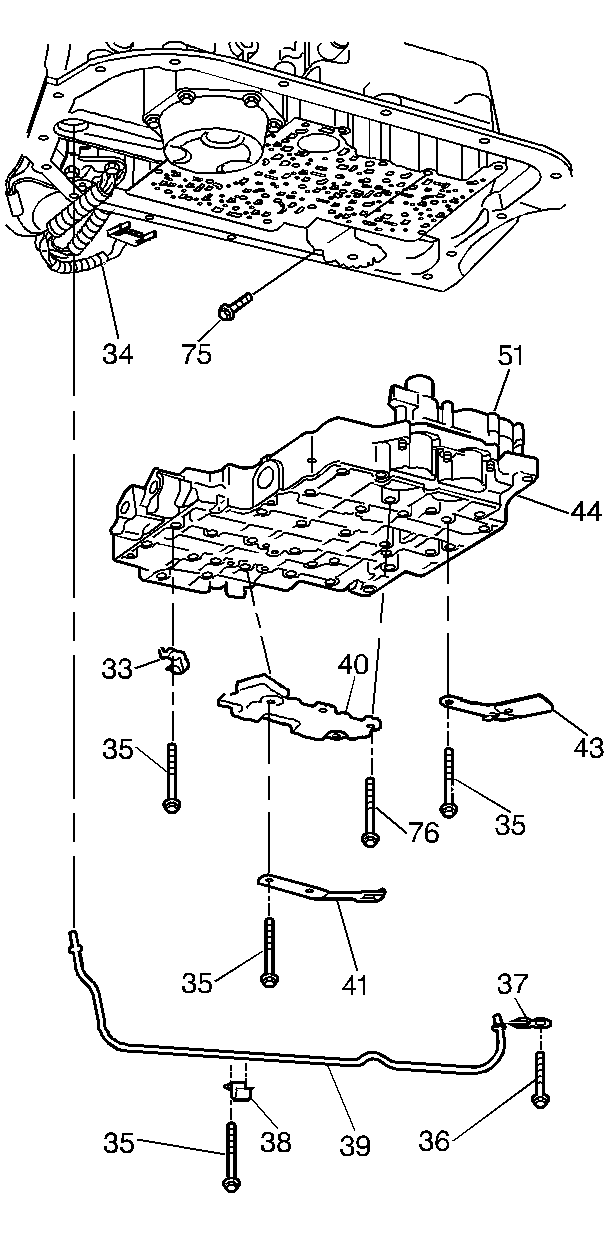
- Install the complete valve body assembly onto the case.
- Be sure to attach the manual shaft to the detent lever and the pin assembly.
- Install the pressure switch manifold (PSM) onto the valve body assembly.
- Install the spring and roller assembly into place.
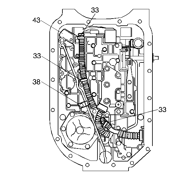
- Install the three wiring clips and the fluid indicator stop.
- Install the twenty-one bolts using a 10-mm socket.
- Install the six bolts using an 8-mm socket into the PSM (Pressure Switch Manifold).
- Attach the wiring harness to the six connectors. (Put the large end into the case first.):
- Install the lube pipe long end into the case.
- Install the lube pipe clip with the short bolt.
- Install the twenty-one bolts using a 10-mm socket in order to attach the valve body to the case.
- Install the transmission oil pan and the transmission oil filter. Refer to Automatic Transmission Fluid and Filter Replacement
- Raise the transmission if the transmission was lowered for clearance.
- Remove the safety stands.
- Lower the vehicle.
- Connect the battery negative cable assembly to the battery negative terminal.
Tighten
Tighten the bolts to 11 N·m(96 lb in).
Notice: Use the correct fastener in the correct location. Replacement fasteners must be the correct part number for that application. Fasteners requiring replacement or fasteners requiring the use of thread locking compound or sealant are identified in the service procedure. Do not use paints, lubricants, or corrosion inhibitors on fasteners or fastener joint surfaces unless specified. These coatings affect fastener torque and joint clamping force and may damage the fastener. Use the correct tightening sequence and specifications when installing fasteners in order to avoid damage to parts and systems.
Tighten
Tighten the bolts to 11 N·m(96 lb in).
| • | The pressure switch |
| • | Solenoid A (1/2) |
| • | Solenoid B (2/3) |
| • | The temperature sensor |
| • | The PWM solenoid |
| • | The force motor |
Tighten
Tighten the bolt to 11 N·m (96 lb in).
Tighten
Tighten the bolts to 11 N·m (96 lb in).
Tighten
Tighten the terminal bolt to 15 N·m (11 lb ft).
