DTC P0741 TCC System Stuck Off 6.5L Diesel

Circuit Description
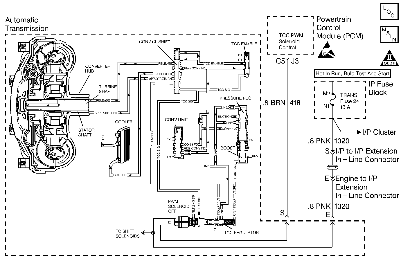
The PCM energizes the TCC PWM Solenoid Valve by creating a ground path on circuit 418. When the PCM grounds (energizes) the TCC PWM Sol. Valve, the TCC PWM Sol. Valve stops the converter signal oil from exhausting. This causes the converter signal oil pressure to increase and shift the TCC valve. The TCC PWM Sol. Valve will de-energize when the PCM no longer provides a ground path. When the TCC PWM Sol. Valve is de-energized, the TCC PWM Sol. Valve exhausts fluid and releases the TCC.
If the PCM detects high torque converter slip when the TCC is commanded ON, then DTC P0741 sets. DTC P0741 is a type A DTC.
Conditions for Setting the DTC
| • | No APP Sensor DTCs P0121, P0122, P0220, P0221, P0222, P0223, P0225, P0226, P0227, or P0228. |
| • | No OSS Sensor DTCs P0722 or P0723. |
| • | No ISS Sensor DTCs P0716 or P0717. |
| • | No TCC PWM Sol. Valve DTCs P0742 or P1860. |
| • | No TFP Val. Position Sw. DTC P1810. |
| • | The TCC PWM Sol. Valve is commanded in 2nd or 3rd or greater than 0.6 seconds. |
| • | The engine must be running for at least 5 seconds. |
| • | The TCC is applied for greater than 0.6 seconds. |
| • | The gear ratio must indicate 2nd or 3rd gear. |
| • | The Throttle Position is greater than 20%. |
| • | The TFP Val. Position Sw. must be in D4, D3, or D2. |
| • | The TFT must be -10 to +150°C (14-302°F). |
| • | The TCC slip speed is greater than 65 RPM for 4 seconds. |
| • | All conditions must be met for a total of 2 occurrences. |
Action Taken When the DTC Sets
| • | The PCM inhibits the TCC. |
| • | The PCM inhibits 4th gear. |
| • | The PCM illuminates the Malfunction Indicator Lamp (MIL). |
Conditions for Clearing the MIL/DTC
- The PCM turns OFF the MIL after three consecutive ignition cycles without a failure reported.
- A scan tool can clear the DTC from the PCM history. The PCM clears the DTC from the PCM history if the vehicle completes 40 warm-up cycles without a failure reported.
- The PCM cancels the DTC default actions when the fault no longer exists and the ignition is OFF long enough in order to power down the PCM
Diagnostic Aids
| • | Inspect the wiring for poor electrical connections at the PCM Inspect the wiring for poor electrical connections at the transmission 20-way connector. Look for the following conditions: |
| - | A bent terminal |
| - | A backed out terminal |
| - | A damaged terminal |
| - | Poor terminal tension |
| - | A chafed wire |
| - | A broken wire inside the insulation |
| • | First diagnose and clear any engine DTCs or APP Sensor codes that are present. Then inspect for any transmission DTCs that may have reset. |
Step | Action | Value(s) | Yes | No | ||||
|---|---|---|---|---|---|---|---|---|
1 | Was the Powertrain On-Board Diagnostic (OBD) System Check performed? | -- | ||||||
2 |
Important: Before clearing the DTCs, use the scan tool in order to record the Freeze Frame and Failure Records for reference. The Clear Info function will erase the data. Is the TCC snapshot data greater than the specified value when the TCC PWM Sol. Valve is commanded ON for greater than 2 seconds? | 65 RPM | Go to Diagnostic Aids | |||||
3 | Inspect the TCC PWM Sol. Valve for being mechanically stuck OFF. Refer to Torque Converter Clutch Diagnosis in this Section. Did you find a problem? | -- | ||||||
4 |
Did you find and correct a problem? | -- | -- | |||||
5 | In order to verify your repair, perform the following procedure:
Has the test run and passed? | -- | System OK |
DTC P0741 TCC System Stuck Off 4.3L, 5.7L, and 7.4L Gas

Circuit Description
Important: DTC P0741 inspects for high TCC slip in 2nd and 3rd gear only. The transmission must be in hot mode or experiencing a wide open throttle maneuver in order for the TCC apply to occur in 2nd and 3rd gear.
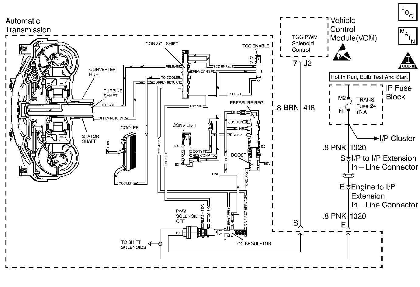
The VCM energizes the Torque Converter Clutch Pulse Width Modulated Solenoid Valve by creating a ground path on circuit 422. When the VCM grounds (energizes) the TCC PWM Sol. Valve, the TCC PWM Sol. Valve stops the converter signal oil from exhausting. This causes the converter signal oil pressure to increase and shift the TCC valve. The TCC PWM Sol. Valve will de-energize when the VCM no longer provides a ground path. When the TCC PWM Sol. Valve is de-energized, the TCC PWM Sol. Valve exhausts fluid and releases the TCC.
When the VCM detects high torque converter slip when the TCC is commanded ON, then DTC P0741 sets. DTC P0741 is a type D DTC. For California emissions vehicles DTC P0741 is a type A DTC.
Conditions for Setting the DTC
| • | No TP Sensor DTCs P0121 or P0122. |
| • | No VSS DTC P0502. |
| • | No ISS Sensor DTCs P0716 or P0717. |
| • | No TCC DTCs P0742 or P1860. |
| • | No TFP Val. Position Sw. DTC P1810. |
| • | The engine must be running for at least 5 seconds. |
| • | The gear ratio must indicate 2nd, 3rd, or 4th gear. |
| • | The Throttle Position is 10-80% (15-80% for 4.3L). |
| • | The TFP Val. Position Sw. must be in D4, D3, or D2. |
| • | The transmission fluid temperature must be -10 to +150°C (14-302°F). |
| • | The TCC slip speed is greater than 65 RPM for 4 seconds (5 seconds for 4.3L). |
| • | All conditions must be met for a total of 2 occurrences. |
Action Taken When the DTC Sets
| • | The VCM inhibits the TCC. |
| • | The VCM inhibits 4th gear. |
| • | The VCM illuminates the Malfunction Indicator Lamp (MIL) for California emissions vehicles. |
Conditions for Clearing the DTC
| • | For California emissions, the VCM turns OFF the MIL after three consecutive ignition cycles without a failure reported. |
| • | A scan tool can clear the DTC from the VCM history. The VCM clears the DTC from the VCM history if the vehicle completes 40 warm-up cycles without a failure reported. |
| • | The VCM cancels the DTC default actions when the fault no longer exists and the ignition is OFF long enough in order to power down the VCM. |
Diagnostic Aids
| • | Inspect the wiring for poor electrical connections at the VCM. Inspect the wiring for poor electrical connections at the transmission 20-way connector. Look for the following conditions: |
| - | A bent terminal |
| - | A backed out terminal |
| - | A damaged terminal |
| - | Poor terminal tension |
| - | A chafed wire |
| - | A broken wire inside the insulation |
| • | First diagnose and clear any engine DTCs or TP Sensor codes that are present. Then inspect for any transmission DTCs that may have reset. |
Step | Action | Value(s) | Yes | No | ||||
|---|---|---|---|---|---|---|---|---|
1 | Was the Powertrain On-Board Diagnostic (OBD) System Check performed? | -- | Go to Powertrain On Board Diagnostic (OBD) System Check (4.3L) or Powertrain On Board Diagnostic (OBD) System Check (5.7L and 7.4L) | |||||
2 |
Important: Before clearing the DTCs, use the scan tool in order to record the Freeze Frame and Failure Records for reference. The Clear Info function will erase the data. Is the TCC snapshot data greater than the specified value when the TCC PWM Sol. Valve is commanded ON for greater than 4 seconds? | -- | Go to Diagnostic Aids | |||||
3 | The TCC PWM Sol. Valve is mechanically stuck OFF. Refer to Torque Converter Clutch Diagnosis in this Section. Did you find a problem? | -- | ||||||
4 |
Did you find and correct a problem? | -- | -- | |||||
5 | In order to verify your repair, perform the following procedure:
Has the test run and passed? | -- | System OK |
