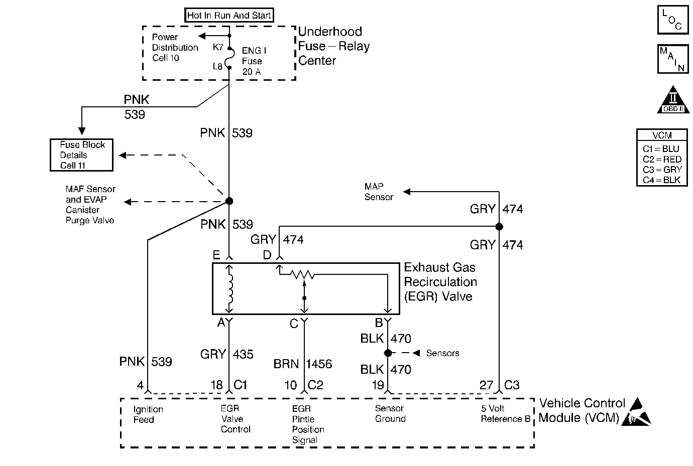
Circuit Description
The VCM tests the exhaust gas recirculation valve by momentarily commanding the valve on while monitoring the MAP. If the expected MAP increase is not seen under certain operating conditions (decel) for a calibrated number of tests, the VCM turns on the MIL (Malfunction Indicator Lamp), and the VCM stores the DTC P0401. This is a type A DTC.
The VCM runs the EGR tests when the following conditions are met:
| • | No TP sensor DTCs set |
| • | No MAP DTCs set |
| • | No VS sensor DTCs set |
| • | No IAT sensor DTCs set |
| • | No ECT sensor DTCs set |
| • | No IAC DTCs set. |
| • | No linear EGR pintle position DTCs set |
| • | No Transmission DTCs set. |
| • | The change in IAC is less than 8 counts |
| • | ECT greater than 78°C |
| • | Baro greater than 70 kPa |
| • | Vehicle speed greater than 30 mph. |
| • | Engine run time is greater than 120 seconds |
| • | AC clutch status is unchanged |
| • | Transmission is in locked or unlocked stage (stable) |
| • | No Misfire DTCs set |
Conditions for Setting the DTC
The following conditions will set the DTC:
| • | The EGR flow test fails if the VCM does not detect a sufficient rise in the MAP during the above conditions. |
| • | The DTC P0401 sets if the VCM does not detect a sufficient rise in the MAP during the above conditions. |
Action Taken When the DTC Sets
With a current DTC set, the VCM turns ON the MIL.
Conditions for Clearing the MIL/DTC
The VCM turns OFF the MIL after 3 consecutive driving trips without a fault condition present. A history DTC will clear if no fault conditions have been detected for 40 warm-up cycles (the coolant temperature has risen 22°C (40°F) from the start-up coolant temperature and the engine coolant temperature exceeds 71°C (160°F) during that same ignition cycle) or the scan tool clearing feature has been used.
Diagnostic Aids
Notice: In order to prevent further damage if the EGR valve shows signs of excessive
heat, check the exhaust system for blockage (possibly a plugged converter)
using the procedure found on the restricted exhaust system check. If the exhaust
system is restricted, repair the cause; one of which might be an injector
which is open due to one of the following reasons:
• Stuck • Grounded driver circuit
Check for the following conditions:
| • | Poor connection or damaged harness - Inspect VCM harness connectors for the following conditions: |
| • | Backed out terminal EGR Control circuit |
| • | Improper mating |
| • | Broken locks |
| • | Improperly formed or damaged terminal |
| • | Poor terminal to wire connection |
| • | Damaged harness |
| • | Intermittent test - If connections and harness check OK, monitor a digital voltmeter connected between terminal EGR Control circuit and ground while moving related connectors and wiring harness. If the failure is induced, the voltage reading will change. |
Test Description
The numbers below refer to the step numbers in the diagnostic table.
-
Ensures that the EGR valve is allowing EGR flow and the VCM is capable of controlling the EGR valve.
-
Ensures that the EGR LOW signal circuit is not shorted to ground.
-
Ensures that the EGR LOW signal circuit is not open and that the VCM quad-driver for the EGR LOW signal circuit is functioning properly.
Step | Action | Value(s) | Yes | No |
|---|---|---|---|---|
1 |
Important: Before clearing DTCs, use the scan tool in order to record the freeze frame and the failure records for reference because the Clear Info function will lose the data. Was the Powertrain On-Board Diagnostic (OBD) System Check performed? | -- | ||
Does the engine run rough as the EGR valve is cycled? | 1500 RPM | |||
Is the test lamp off? | -- | |||
Is the test lamp on as the EGR valve is cycled through 100%? | -- | |||
5 |
Was a problem found? | -- | ||
6 | Refer to the Diagnostic Aids. | -- | -- | -- |
7 | Check for a short to ground in the EGR control circuit. Was a problem found? | -- | ||
8 | Check for a restriction in the EGR tube or passage. Was a problem found? | -- | ||
9 | Check for a poor electrical connection at the EGR valve. Was a problem found? | -- | ||
10 | Replace the EGR valve. Refer to EGR Valve Replacement for the 4.3L. Is the action complete? | -- | -- | |
11 | Check for an open in EGR control circuit. Was a problem found? | -- | ||
12 | Check for an open in EGR power feed circuit. Was a problem found? | -- | ||
13 | Check for a poor connection at the VCM. Was a problem found? | -- | ||
14 | Repair the circuit as necessary. Refer to Wiring Repairs in Engine Electrical. Is the action complete? | -- | -- | |
15 | Replace the VCM. Important: If the VCM is faulty, reprogram the VCM. Refer to VCM Replacement/Programming . Is the repair complete? | -- | -- | |
16 |
Does the scan tool indicate that this diagnostic ran and passed? | -- | ||
17 | Using the scan tool, select the Capture Info and the Review Info. Are any DTCs displayed that have not been diagnosed? | -- | Go to The Applicable DTC Table | System OK |
