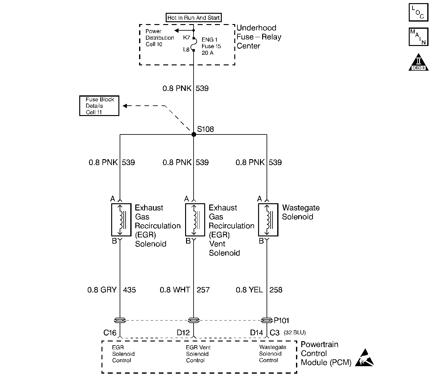
Circuit Description
The turbocharger wastegate is a vacuum actuated valve used to control the exhaust gas heat sent to the turbo. The wastegate pulse width modulated solenoid meters the vacuum level at the wastegate valve actuator as commanded by the PCM. When the PCM is commanding the Wastegate solenoid ON, the voltage potential of the circuit will be low (near 0 volts). When the PCM is commanding the wastegate solenoid OFF, the voltage potential of the circuit will be high (near battery volts). The primary function of the PCM in this circuit is to supply the ground for the wastegate solenoid. This is a type B code.
Conditions for Setting the DTC
| • | PCM requested Wastegate solenoid ON. |
| • | Voltage on Wastegate solenoid control circuit high (near battery volts). |
| • | 2 consecutive faults detected. |
| • | Conditions met for 2 seconds. |
or
| • | PCM requested Wastegate solenoid OFF. |
| • | Voltage on Wastegate solenoid control circuit low (near 0 volts). |
| • | 2 consecutive faults detected. |
| • | Conditions met for 2 seconds. |
Action Taken When the DTC Sets
Low power.
Conditions for Clearing the MIL/DTC
| • | The PCM will turn the MIL off after three consecutive trips without a fault condition. |
| • | A History DTC will clear when forty consecutive warm-up cycles that the diagnostic does not fail (coolant temperature has risen 5°C (40°F) from start up coolant temperature and engine coolant temperature exceeds 71°C (160°F) that same ignition cycle. |
| • | Use of a Scan Tool |
Diagnostic Aids
This diagnostic will set when control circuit does not follow the PCM command (when the solenoid is requested ON voltage will drop, when the solenoid is OFF ignition voltage will be present). The scan tool has a 5 second ON time abort. The wastegate solenoid can be commanded ON for as many times as needed, in 5 second intervals. Its possible DTC P0236 may set along with DTC P1656. This diagnostic can be checked during key up. The engine will not respond to scan tool commands at idle (engine unable to achieve boost pressures greater than BARO at idle) or at any engine speed greater than idle (PCM control abort to prevent engine damage).
Test Description
Number(s) below refer to the Step number(s) on the Diagnostic Table.
-
Be sure that both the ON and OFF states are commanded. Repeat the commands as mant times as necessary.This Step will determine if this DTC is a current or intermittent.
-
This check can detect a partially shorted coil which would cause excessive current flow. Leaving the circuit engerized for 2 minutes allows the coil to warm up. When warm, the coil may open (Amps drop to 'zero', or short (Amp draw greater than 0.75A).
-
Listen for an audible 'click' when the solenoid operates.. This Step checks the ignition feed circuit for an open.
Step | Action | Value(s) | Yes | No |
|---|---|---|---|---|
1 |
Important: Before clearing DTCs use the scan tool Capture Info to record freeze frame and failure records for reference, as data will be lost when Clear Info function is used. Was the On-Board Diagnostic (OBD) System Check performed? | -- | ||
Does Wastegate duty cycle respond to scan tool commands? | -- | |||
Is current draw less then the specified value, but not zero? | 0.75 A | |||
4 |
Does DVM display infinite resistance? | -- | ||
5 |
Does test light turn ON and OFF with each command? | -- | ||
6 |
Is the test light ON? | -- | ||
Does the solenoid operate? | -- | |||
8 | DTC is intermittent. If no additional DTCs are stored, refer to Diagnostic Aids. If additional DTCs were stored refer to the applicable DTC table(s) first. Are any additional DTCs stored? | -- | Go to the Applicable DTC Table | Go to Diagnostic Aids |
9 | Check for a poor connection at the wastegate solenoid and replace terminals as necessary. Did the terminal require replacement? | -- | ||
10 | Repair wastegate solenoid control circuit. Is the action complete? | -- | -- | |
11 | Check for a poor connection at the PCM, wastegate control circuit. Was a problem found? | -- | ||
12 | Repair the open in the ignition feed circuit. Is the action complete? | -- | -- | |
13 | Replace the wastegate solenoid. Refer to Wastegate Solenoid . Is the action complete? | -- | -- | |
14 | Replace the faulty PCM. Important: If the PCM is faulty, the new PCM must be programmed. Refer to Powertrain Control Module Replacement/Programming . Is the action complete ? | -- | -- | |
15 |
Does the scan tool indicate that this diagnostic Ran and Passed? | -- | ||
16 | Using the scan tool, select Capture Info, Review Info. Are any DTCs displayed that have not been diagnosed? | -- | Go to the Applicable DTC Table | System OK |
