Valve Rocker Arm, Shaft, and Push Rod Replacement for Chevrolet Chevy K Pickup - 4WD 1998
Removal Procedure
Important: Rotate the engine until the mark on the crankshaft balancer is at the 2 o'clock position.
Rotate the crankshaft counter clock wise 88 mm (3 1/2 inch), aligning the crankshaft balancer mark with the first lower water pump bolt, about 12:30. This will position the engine so that no valves are close to the piston crown.- Disconnect the battery negative cables from the batteries. Refer to Battery Cable .
- Remove the upper intake manifold from the lower intake manifold. Refer to Intake Manifold Replacement .
- Remove the lower intake manifold from the cylinder heads. Refer to Intake Manifold Replacement .
- Remove the valve rocker arm cover from the cylinder head. Refer to Valve Rocker Arm Cover Replacement .
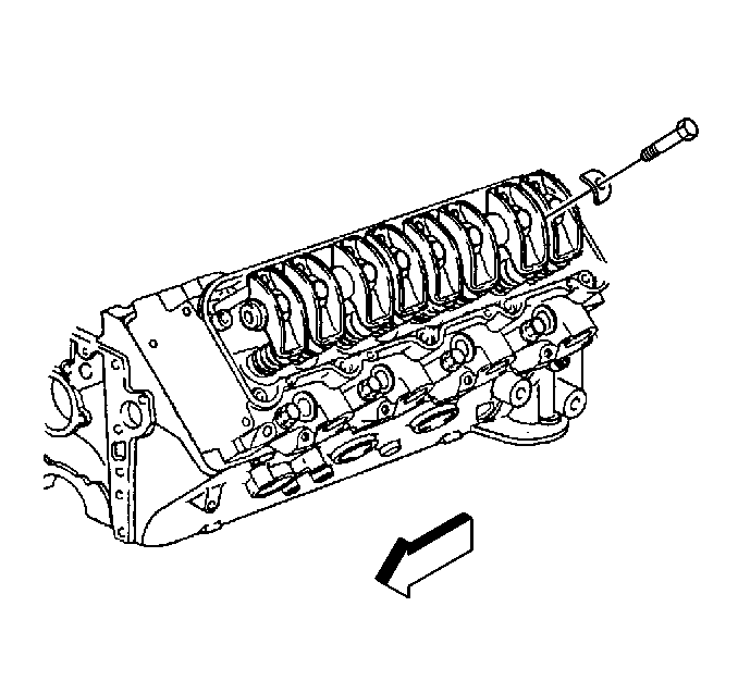
- Remove the valve rocker arm shaft bolts from the cylinder head.
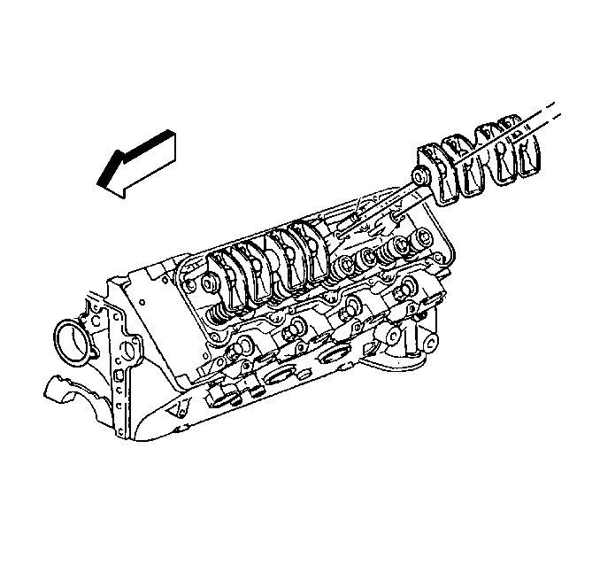
- Remove the valve rocker arm shaft with the valve rocker arm.
- Remove the push rods from the engine block.
- Remove the valve rocker arms from the cylinder head.
- Insert a screwdriver into the valve rocker arm shaft bore and break off the end of the nylon valve rocker arm retainers.
- Remove the valve rocker arm retainers with a pair of pliers.
- Slide the valve rocker arms from the rocker arm shaft.
Notice: All valve train components must be reassembled in the exact order and position from which they were removed.
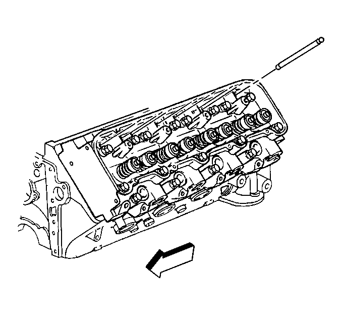
Important: The push rods must be installed in the original direction as disassembly. This is because the push rods have different degrees of hardness at each end. A paint stripe identifies the upper end of the push rod. If the paint stripe is not visible, mark the push rod on the upper end as the push rods are removed.
Installation Procedure
Notice: All valve train components must be reassembled in the exact order and position from which they were removed.
Important: Lubricate the valve rocker arms with clean engine oil before installing.
- Install the push rod, with the painted or marked end up to the engine block.
- Install the valve rocker arms to the valve rocker arm shaft (one type of valve rocker arm is used at all locations).
- Install the valve rocker arm retainers to the cylinder head.
- Center the valve rocker arm on the corresponding holes in the valve rocker arm shaft.
- Use a drift of at least 13 mm (1/2 inch) in diameter to install new retainers to the valve springs.
- Install the valve rocker arm shaft assembly to the cylinder head.
- Install the valve rocker arm shaft bolts to the cylinder head.
- Install the valve rocker arm cover to the cylinder head. Refer to Valve Rocker Arm Cover Replacement .
- Install the lower intake manifold to the cylinder heads. Refr to Intake Manifold Replacement .
- Install the upper intakew manifold to the lower intake manifold. Refer to Intake Manifold Replacement .
- Connect the battery negative cable to the battery. Refer to Battery Cable in Engine Electrical.
Notice: Install the valve pushrods with the copper-colored, painted, or marked end up in order to avoid damage or premature wear.
Notice: Improper installation of the valve rocker arm shaft bolts may cause valve rocker arm shaft breakage and piston to valve contact.
Notice: Use the correct fastener in the correct location. Replacement fasteners must be the correct part number for that application. Fasteners requiring replacement or fasteners requiring the use of thread locking compound or sealant are identified in the service procedure. Do not use paints, lubricants, or corrosion inhibitors on fasteners or fastener joint surfaces unless specified. These coatings affect fastener torque and joint clamping force and may damage the fastener. Use the correct tightening sequence and specifications when installing fasteners in order to avoid damage to parts and systems.
Tighten
Tighten the bolts to 55 N·m (40 lb ft).
