For 1990-2009 cars only
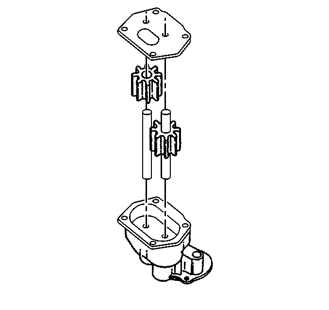
- Install the driven gear.
- Install the idler shaft.
- Install the drive gear with the shaft. Align the marks made during disassembly.
- Install the spacer plate.
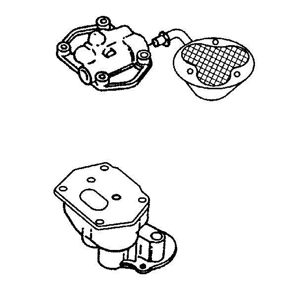
- Install the oil pump cover.
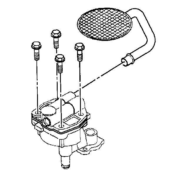
- Install the oil pump cover screws.
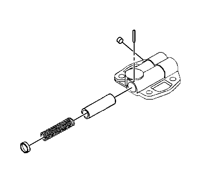
- Install the pressure regulator valve.
- Install the spring.
- Install the roll pin.
- Install the pick-up tube and screen assemble if necessary. Align the tube in the same location as removed from.
- Prime the oil pump by filling the cavity with clean engine oil.
- Inspect the oil pump.
Notice: Use the correct fastener in the correct location. Replacement fasteners must be the correct part number for that application. Fasteners requiring replacement or fasteners requiring the use of thread locking compound or sealant are identified in the service procedure. Do not use paints, lubricants, or corrosion inhibitors on fasteners or fastener joint surfaces unless specified. These coatings affect fastener torque and joint clamping force and may damage the fastener. Use the correct tightening sequence and specifications when installing fasteners in order to avoid damage to parts and systems.
Tighten
Tighten the bolts to 16 N·m (12 lb ft).
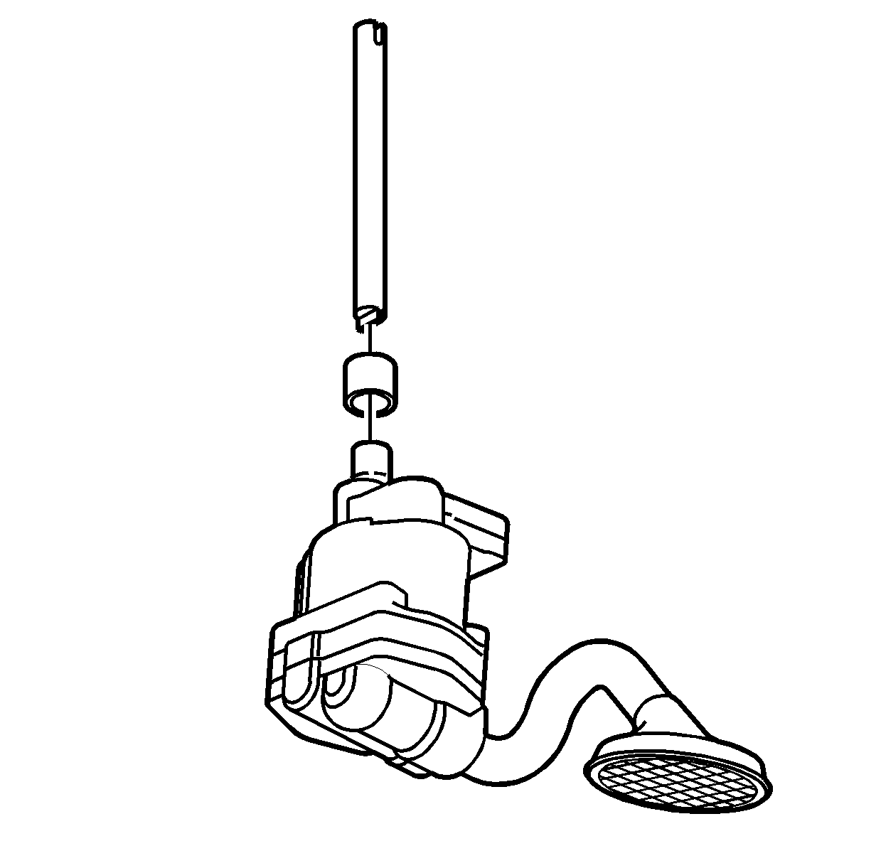
| • | Turn the drive shaft by hand and check for smooth rotation. |
| • | If the oil pump does not rotate smoothly, check for proper assembly. |
| • | If necessary replace the oil pump assembly. |
