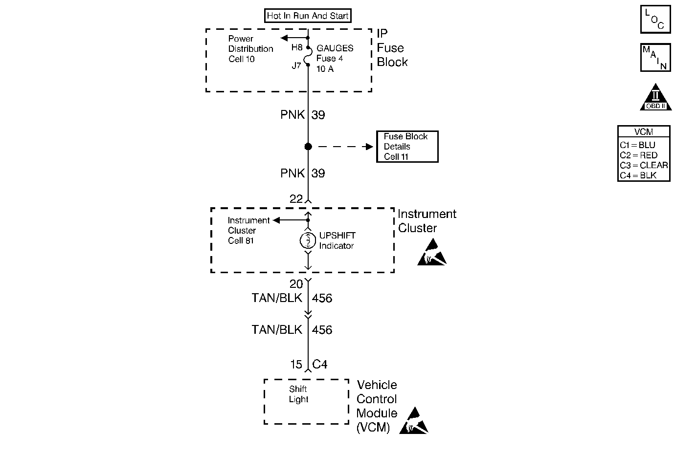
Circuit Description
The control module controls the shift lamp using the following inputs:
| • | The Engine Coolant Temperature (ECT) sensor |
| • | The Throttle Position (TP) sensor |
| • | The Vehicle Speed sensor (VSS) |
| • | The Engine RPM |
The control module uses the measured RPM and the vehicle speed in order to calculate what gear the vehicle is in. This calculation determines when the shift lamp should be turned ON.
Diagnostic Aids
Intermiitent conditions can be cause by wiring problems.
An intermittent may be caused by any of the following conditions:
| • | A poor connection |
| • | Rubbed through wire insulation |
| • | A broken wire inside the insulation |
Thoroughly check any circuitry that is suspected of causing the intermittent complaint. Refer to Intermittents and Poor Connections Diagnosis in Wiring Systems.
If a repair is necessary, refer to Wiring Repairs or Connector Repairs in Wiring Systems.
Test Description
The numbers below refer to the step numbers on the diagnostic table.
Step | Action | Value(s) | Yes | No |
|---|---|---|---|---|
Was the Powertrain On-Board Diagnostic (OBD) System Check performed? | -- | |||
2 |
Is the shift lamp ON? | -- | ||
3 |
Is the shift lamp ON? | -- | ||
4 | Using the scan tool, command the shift lamp OFF and ON. Does the shift lamp respond to the scan tool command? | -- | System OK | |
5 | Check the terminal connect at the control module for the shift lamp control circuit. Was a problem found? | -- | ||
6 | Repair the open in the shift lamp circuit. Is the action complete? | -- | -- | |
7 | Repair as necessary. Is the action complete? | -- | -- | |
8 |
Is the shift lamp ON? | -- | ||
9 | Repair the short to ground in the shift lamp control circuit. Is the action complete? | -- | -- | |
10 |
Refer to Crankshaft Position System Variation Learn . Is the action complete? | -- | -- | |
11 | Using the scan tool, select Capture Info, Review Info. Are any additional DTCs displayed that have not been diagnosed? | -- | Go to the Applicable DTC Table | System OK |
