Differential Overhaul 8.6, 9.5 Inch Axles
Disassembly Procedure
- Remove the differential side bearings. Refer to Differential Side Bearings Replacement .
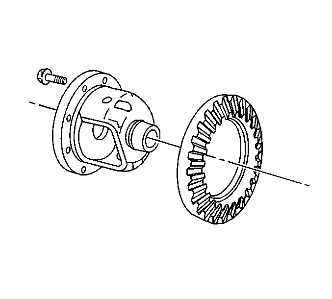
- Remove the ring gear bolts. Discard the bolts.
- Remove the ring gear from the differential. Drive the gear off with a brass drift if necessary.
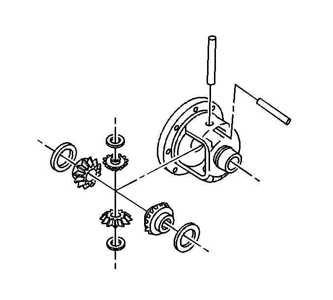
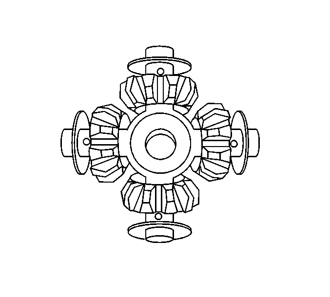
- Remove the differential pinion gears and the differential side gears by doing the following:
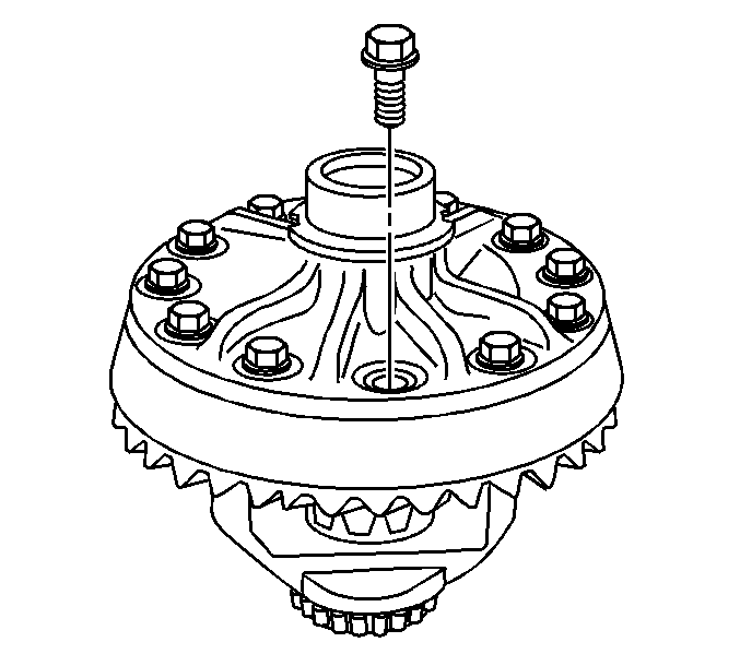
Important: The ring gear bolts have left-hand threads.
Notice: Refer to Ring Gear Removal Notice in the Preface section.
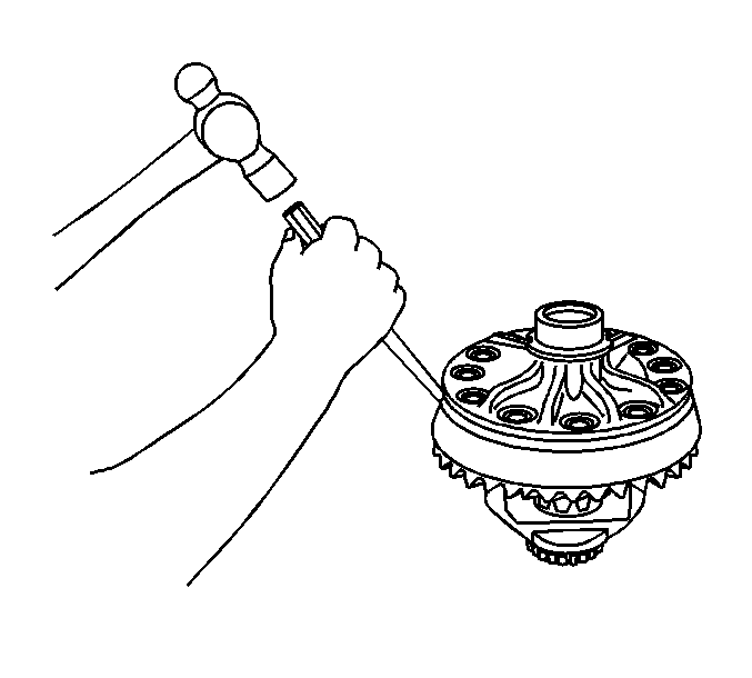
| 4.1. | Remove the pinion shaft lock bolt |
| 4.2. | Remove the pinion shaft. |
| 4.3. | Roll the differential pinion gear out of the case with the pinion thrust washers. |
| 4.4. | Remove the differential side gears and the side gear thrust washers. |
Mark the pinion gears top and bottom and the differential side gears left and right.
Assembly Procedure
- Lubricate all the parts using axle lubricant. Refer to Fluid and Lubricant Recommendations in Maintenance and Lubrication.
- Install the thrust washers to the differential side gears.
- Install the differential side gears and thrust washers into the differential case.
- Install the differential pinion gears by doing the following:
- Install the thrust washers.
- Install the pinion shaft.
- Install a new pinion shaft lock bolt.
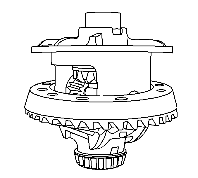
- Install the ring gear to the differential case.
- Install the new ring gear bolts.
- Tighten the new ring gear bolts. Tighten the ring gear bolts alternately and in stages, gradually pulling the ring gear onto the differential case.
- Install the differential side bearings. Refer to Differential Side Bearings Replacement .
If the same differential side gears and the thrust washers are being used, install the gears and the thrust washers to the original locations.
| 4.1. | Position one pinion gear between the differential side gears. |
| 4.2. | Rotate the differential side gears until the pinion gear is directly opposite the opening in the differential case. |
| 4.3. | Place the other pinion gear between the differential side gears. |
Line up the hole in both the pinion gears.
Rotate the pinion gears toward the opening in order to permit the sliding in of the thrust washers.
Notice: Refer to Fastener Notice in the Preface section.
Tighten
| • | For the 8.6 inch axle, tighten the pinion shaft lock bolt to 36 N·m (27 lb ft). |
| • | For the 9.5 inch axle, tighten the pinion shaft lock bolt to 50 N·m (37 lb ft). |
Important: The mating surface of the ring gear and the differential case must be clean and free of burrs before installing the ring gear.
Important: The ring gear bolts have left-hand threads.
Hand start each bolt to ensure that the ring gear is properly installed to the differential case.
Tighten
| • | For the 8.6 inch axle, tighten the ring gear bolts in sequence to 120 N·m (89 lb ft). |
| • | For the 9.5 inch axle, tighten the ring gear bolts in sequence to 140 N·m (103 lb ft). |
Differential Overhaul 11 Inch Axle
Disassembly Procedure
Tools Required
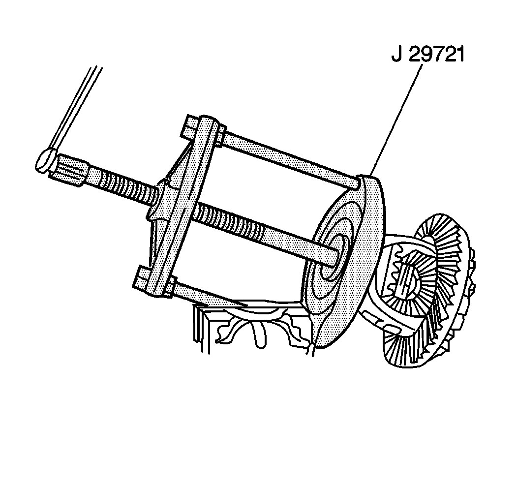
| • | J 8107-2 Side Bearing Puller Plug |
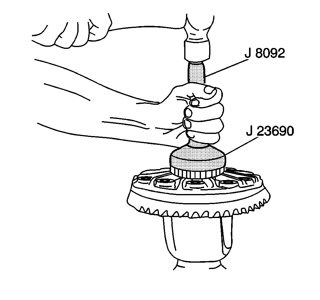
| • | J 23690 Bearing Installer |
| • | J 29721 Differential Side Bearing Remover |
| • | J 29721-70 Side Bearing Adapters |
| • | J 8092 Driver Handle |
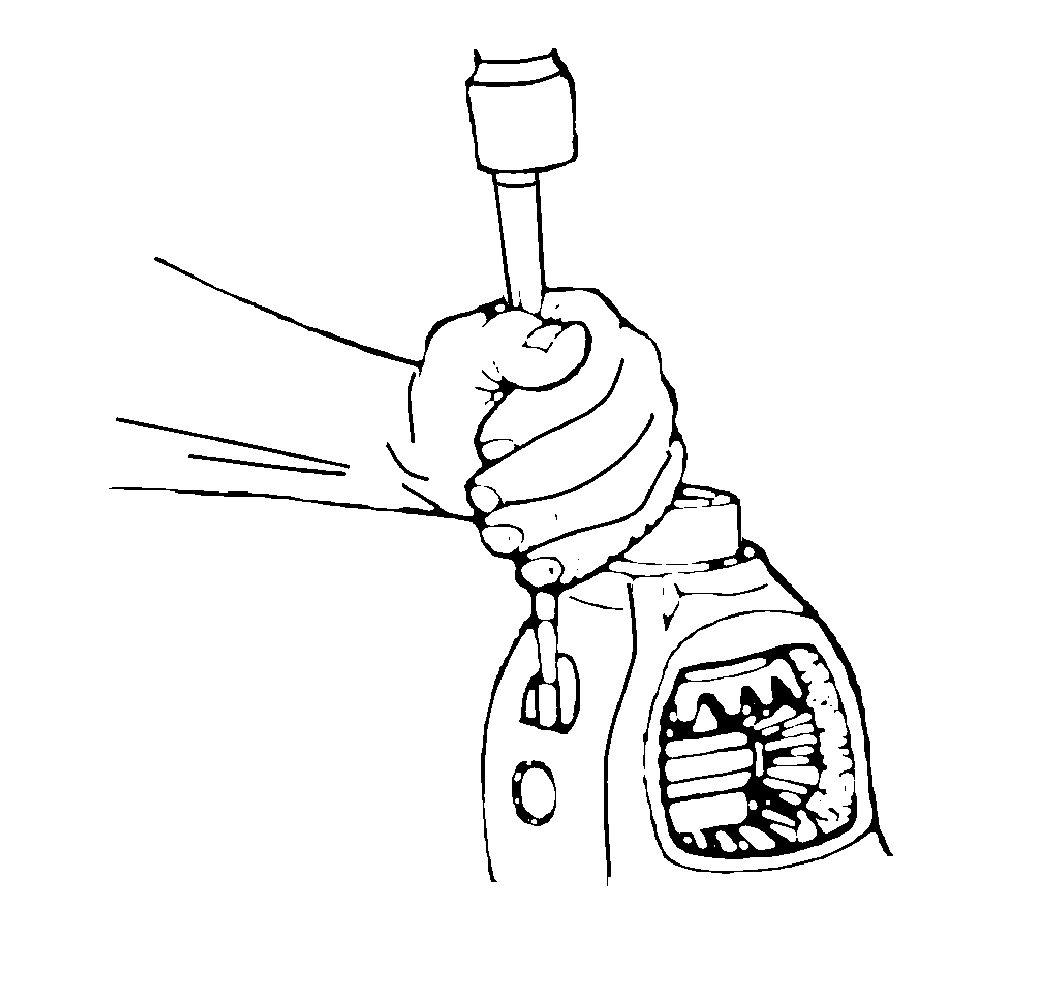
- Remove the differential side bearings using the J 8107-2 , the J 29721 and the J 29721-70 .
- Remove the inboard spacer.
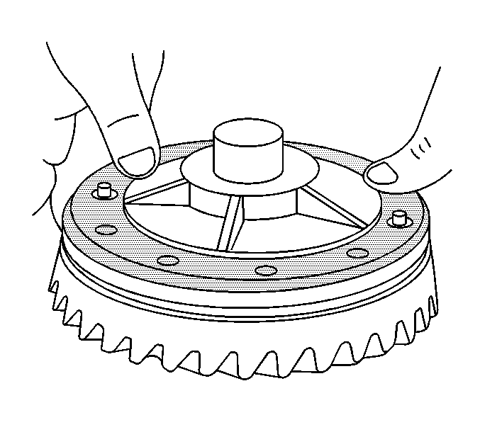
- Remove the ring gear bolts.
- Remove the ring gear from the differential case assembly.
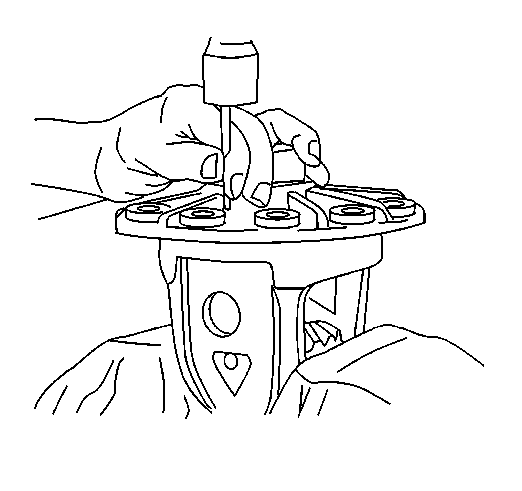
- Remove the pinion shaft lock pin using a hammer and a punch.
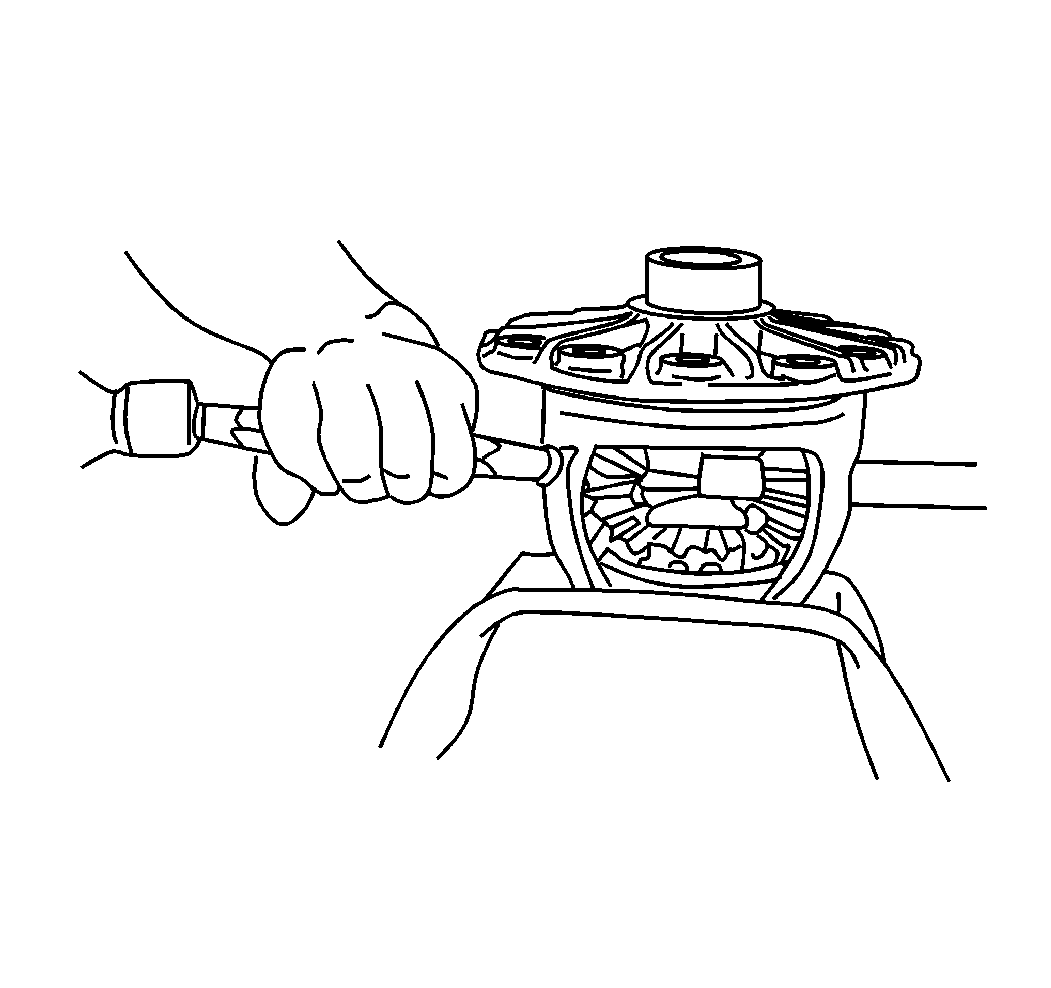
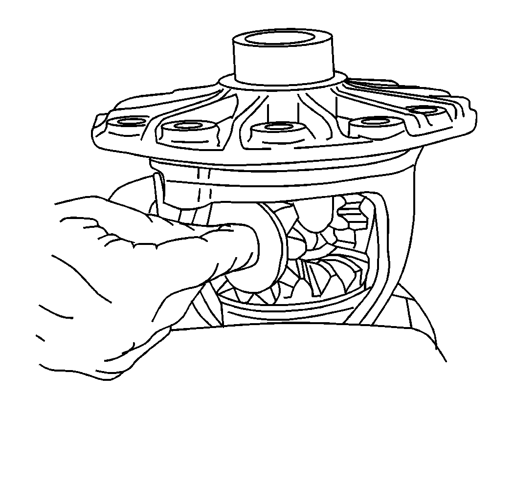
- Remove the pinion shaft using a hammer and brass drift.
- Rotate the side gears until the pinion gears are in the opening of the case. Remove the pinion gears and thrust washers.
- Remove the side gears and the thrust washers.
Important: Mark the side bearings, the outboard shims, and the bearing cups appropriately and place with the corresponding bearing cap.
Important: Mark the inboard spacer left or right and place with the corresponding bearing cup and bearing cap.
Discard the ring gear bolts.
Notice: Do not pry the ring gear from the case. This will damage the ring gear and differential case.
Important: Mark the pinion gears and the thrust washers top and bottom.
Important: Mark the side gears and the thrust washers left and right
Assembly Procedure
- Lubricate all parts with an axle lubricant (GM P/N 12346140 or equivalent).
- Install new thrust washers to the side gears.
- Install the side gears to the differential case assembly.
- Install the pinion gears to the differential without the thrust washers.
- Rotate the pinion gears toward the differential opening in order to allow enough space for the pinion gear thrust washers to slide in.
- Install the new pinion gear thrust washers.
- Rotate the pinion gears into place. Verify that the pinion gears line up with the pinion shaft holes.
- Install the pinion shaft.
- Align the pinion shaft lock pin hole with the hole in the differential case assembly and the pinion shaft.
- Install the new pinion shaft lock pin.
- Peen the metal from the case over the pinion shaft lock pin in two places that are 180 degrees apart.
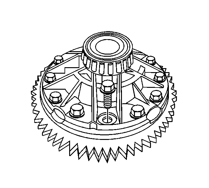
- Install the ring gear to the differential case assembly.
- Install new ring gear bolts. Tighten the ring gear bolts alternately and in stages, gradually pulling the ring gear onto the differential case assembly.
- Install one new hardened 0.689-0.838 mm (0.027-0.033 in) inboard spacer onto each side of the differential case assembly.
- Install the differential side bearings using the J 23690 and the J 8092 .
Important: Install the side gears to the same side that the side gears were on when removed.
Important: Install the pinion gears to the same side that the pinion gears were on when removed.
| 4.1. | Install the pinion gears to the side gears so that the holes in the pinion gears are 180 degrees apart. |
| 4.2. | Rotate the pinion gears into place. Verify that the pinion gears line up with the pinion shaft holes. |
Important: The mating surface of the ring gear and the differential case assembly must be clean and free of burrs before installing the ring gear.
Align the holes in the differential case assembly and the holes in the ring gear.
Notice: Use the correct fastener in the correct location. Replacement fasteners must be the correct part number for that application. Fasteners requiring replacement or fasteners requiring the use of thread locking compound or sealant are identified in the service procedure. Do not use paints, lubricants, or corrosion inhibitors on fasteners or fastener joint surfaces unless specified. These coatings affect fastener torque and joint clamping force and may damage the fastener. Use the correct tightening sequence and specifications when installing fasteners in order to avoid damage to parts and systems.
Tighten
Tighten the ring gear bolts in sequence to 298 N·m (220 lb ft).
Important: The spacer must be the same size as the spacer that was removed.
Measure the spacer thickness using a micrometer to verify the spacer size.
Differential Overhaul 10.5 Inch Axle
Disassembly Procedure
- Remove the differential side bearings. Refer to Differential Side Bearings Replacement .
- Remove the ring gear bolts.
- Remove the ring gear from the differential case.
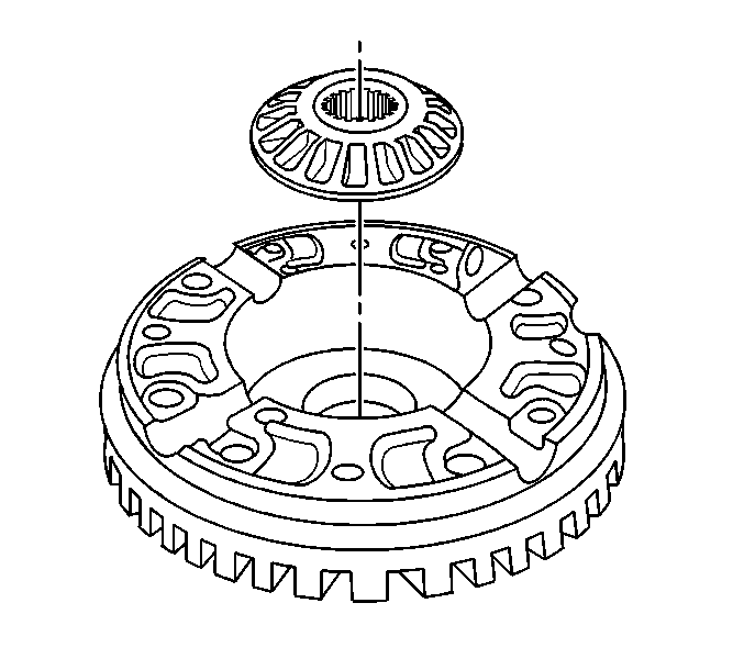
- Separate the differential case assembly.
- Remove the following from the differential case:
- Remove the differential side gears.
Important: The ring gear bolts have left-hand threads.
Notice: Refer to Ring Gear Removal Notice in the Preface section.
Drive the ring gear off with a brass drift if necessary.
Important: If the differential pinion gears, the differential side and the thrust washers are to be reused, mark the components so they can be re-installed in their original location in the differential case.
| • | The thrust washers |
| • | The differential pinion gears |
| • | The differential pinion spider |
Assembly Procedure
- Lubricate the differential side gears and the differential pinion gears with axle lubricant. Use the proper fluid. Refer to Fluid and Lubricant Recommendations in Maintenance and Lubrication.
- Install the differential side gears into the differential case.
- Assemble the differential pinion gears and the thrust washers to the differential spider as shown.
- Assemble the differential case halves.
- Install the ring gear to the differential case.
- Install the new ring gear bolts.
- Tighten the ring gear bolts. Tighten the bolts alternately and in stages, gradually pulling the ring gear onto the differential case.
- Install the differential side bearings. Refer to Differential Side Bearings Replacement .
If the original differential side gears are being used, install the gears in the original location.
If the original differential pinion gears, the thrust washers and the differential spider are being used, install the components in the original locations.
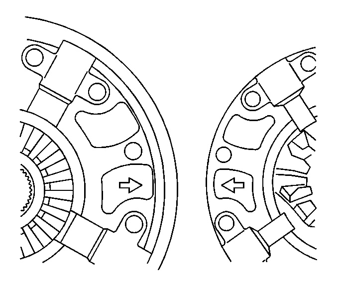
Align the arrow in the differential case as shown.
Important: The mating surface of the ring gear and the differential case must be clean and free of burrs before installing the ring gear.
Notice: Refer to Fastener Notice in the Preface section.
Hand start each bolt in ensure the ring gear is properly installed to the differential case.
Tighten
Tighten the ring gear bolts in sequence to 165 N·m (122 lb ft).
