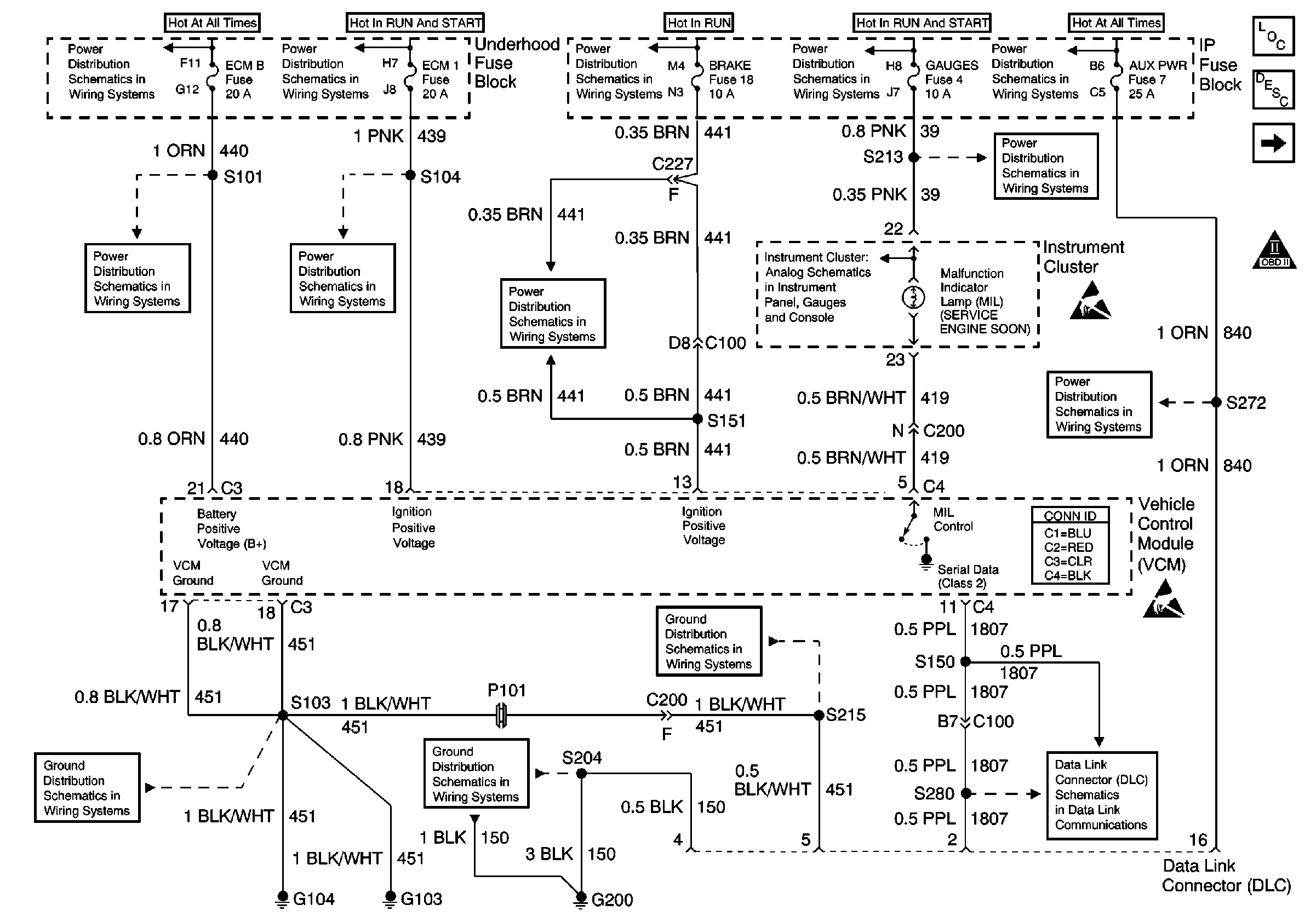
| Figure 1: |
VCM and DLC Power and Grounding, MIL Circuit
|
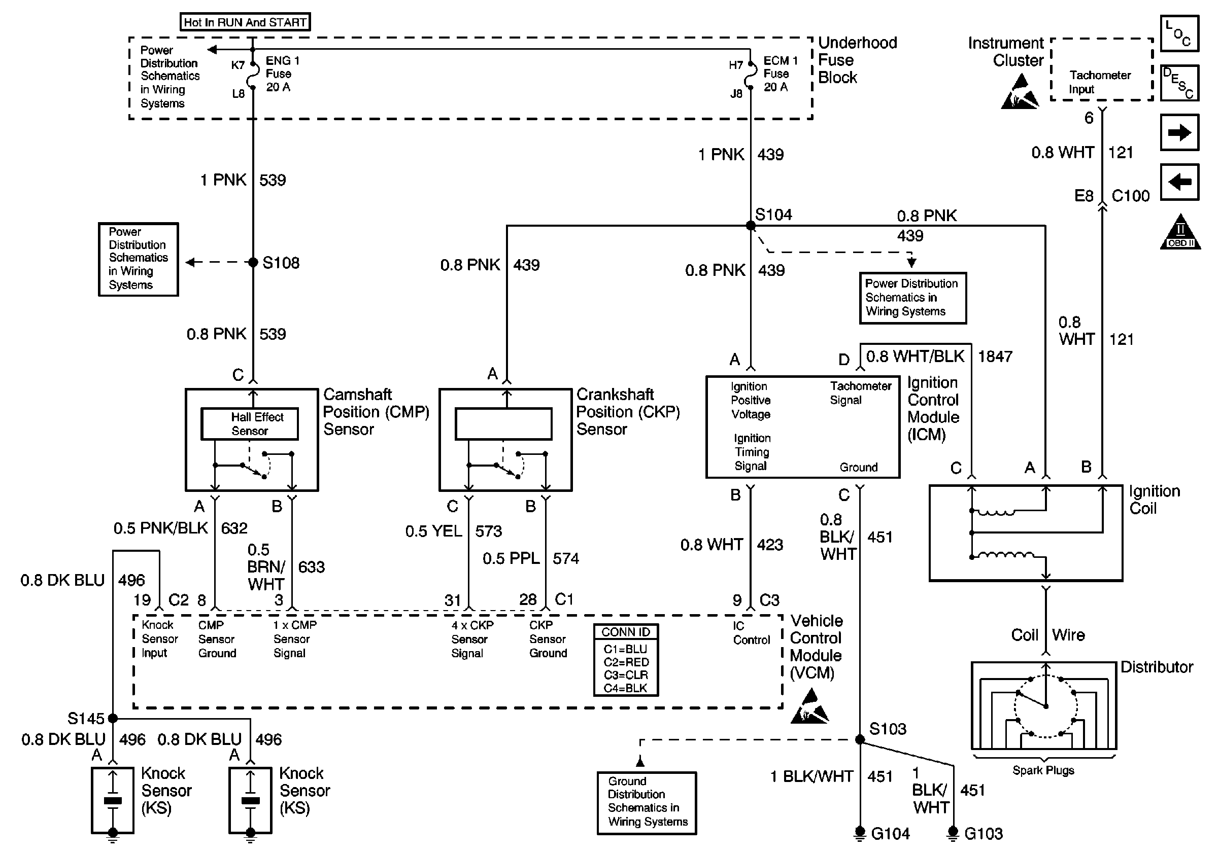
| Figure 2: |
Ignition System
|
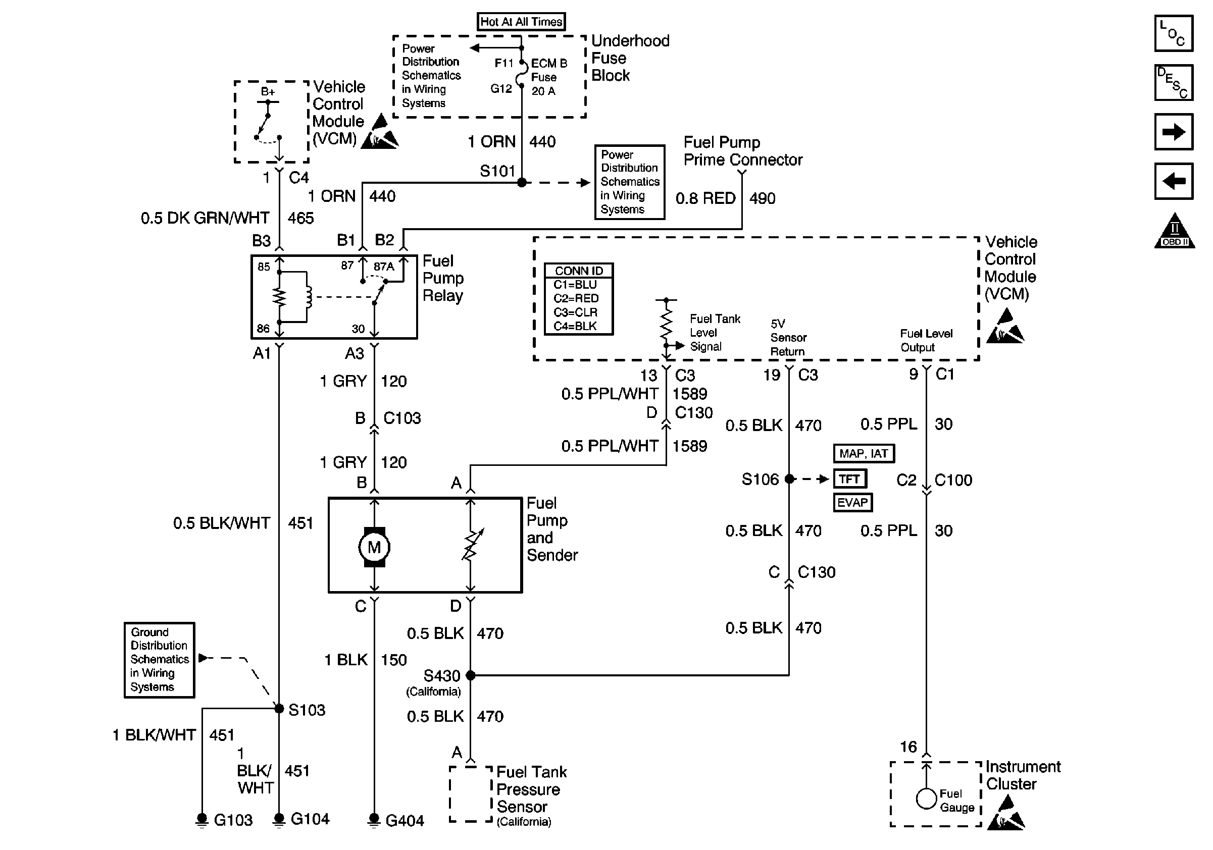
| Figure 3: |
Fuel Pump Control--Single Tank
|
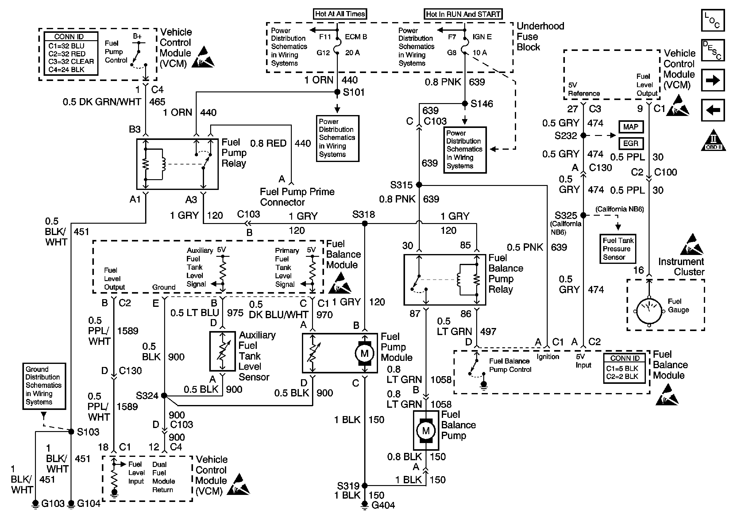
| Figure 4: |
Fuel Pump Control -- Dual Tanks
|
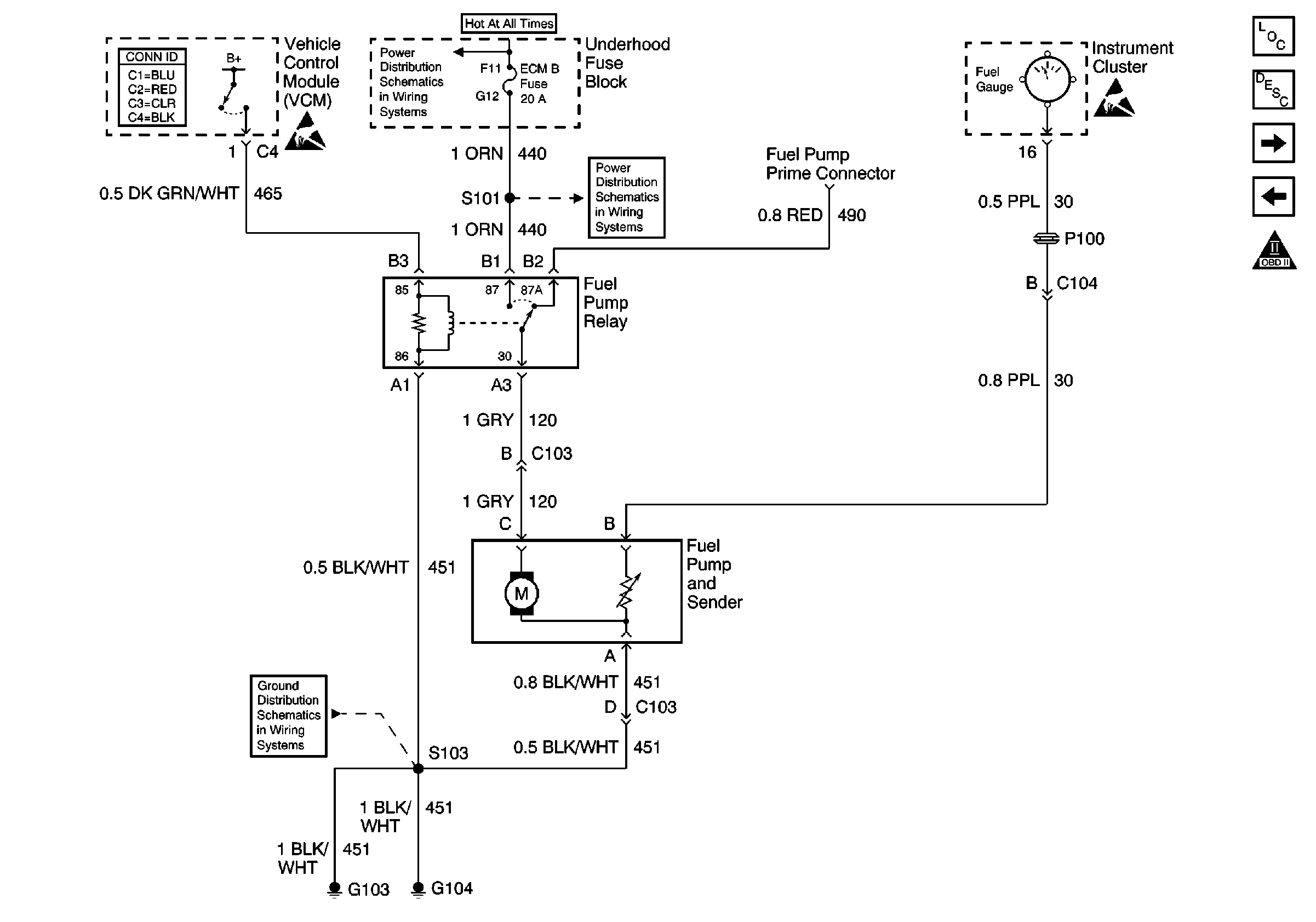
| Figure 5: |
EXPORT--Fuel Pump Control, Single Tank
|
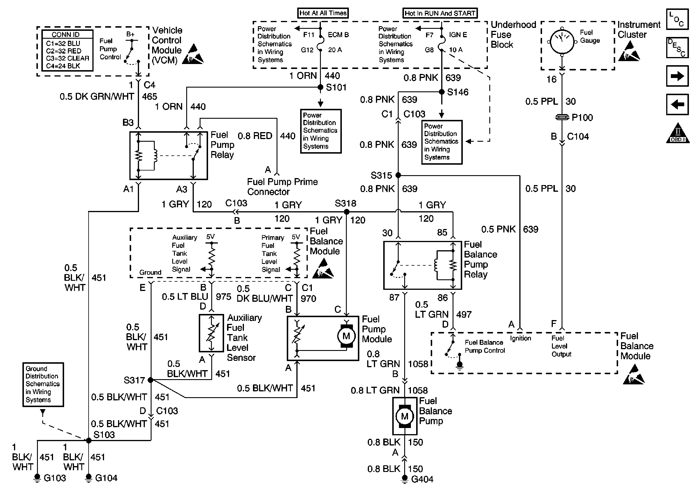
| Figure 6: |
EXPORT--Fuel Pump Control, Dual Tanks
|
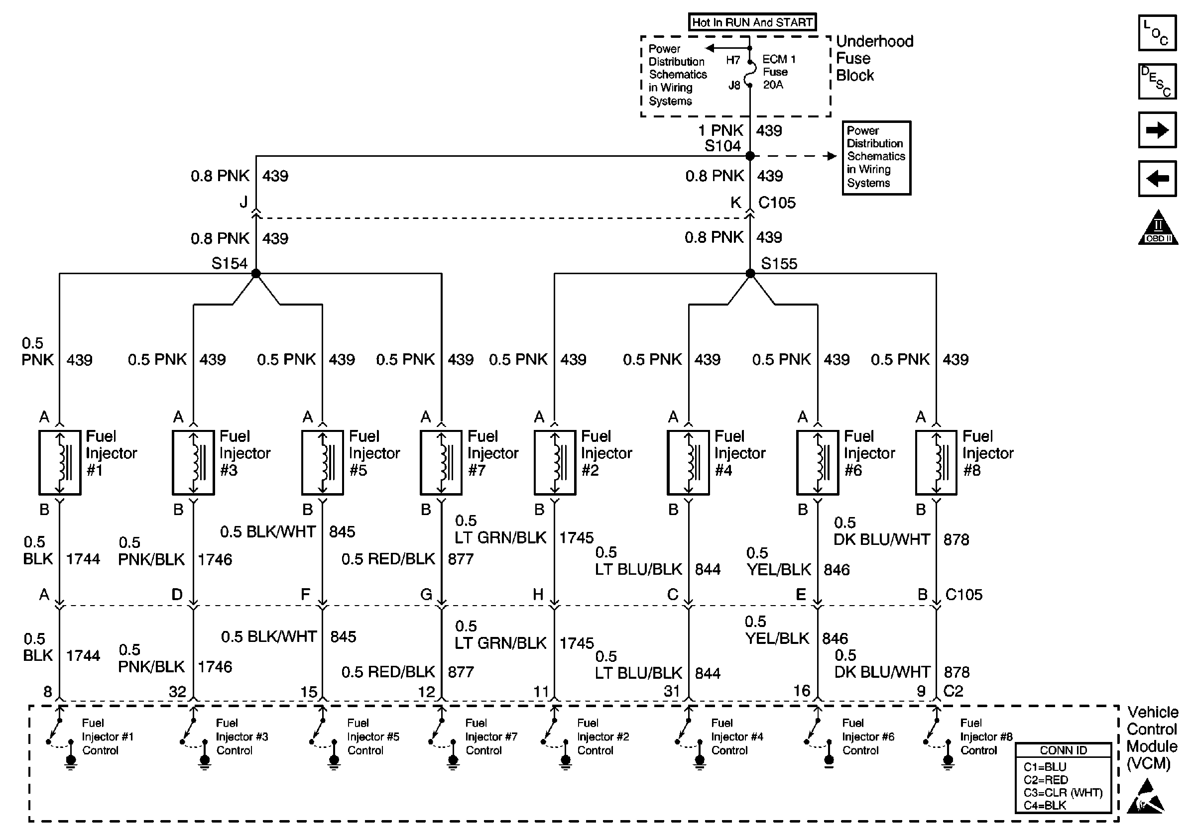
| Figure 7: |
Fuel Injector Controls
|
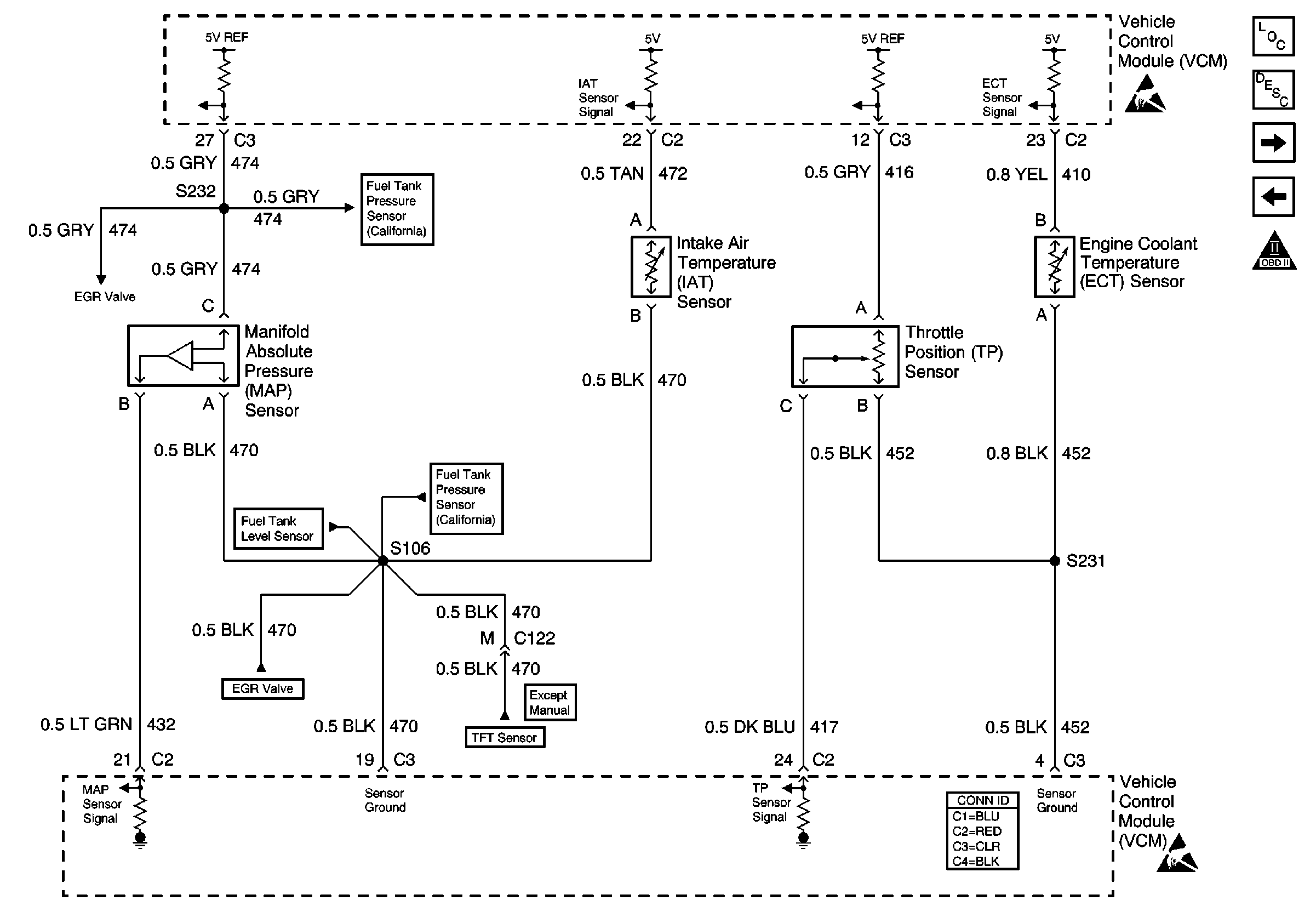
| Figure 8: |
Engine Data Sensors
|
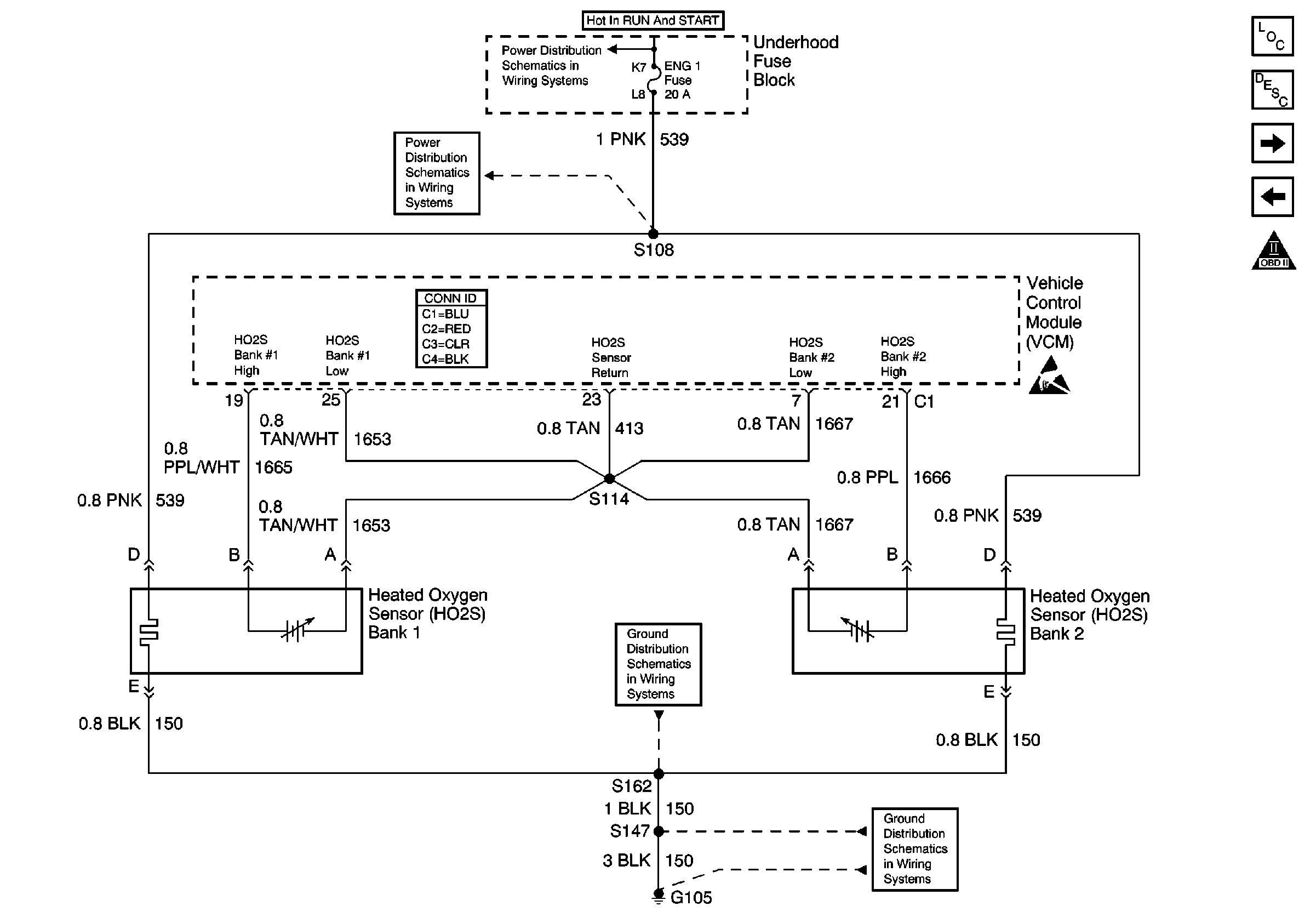
| Figure 9: |
Heated Oxygen Sensors, Federal Emissions (NF2)
|
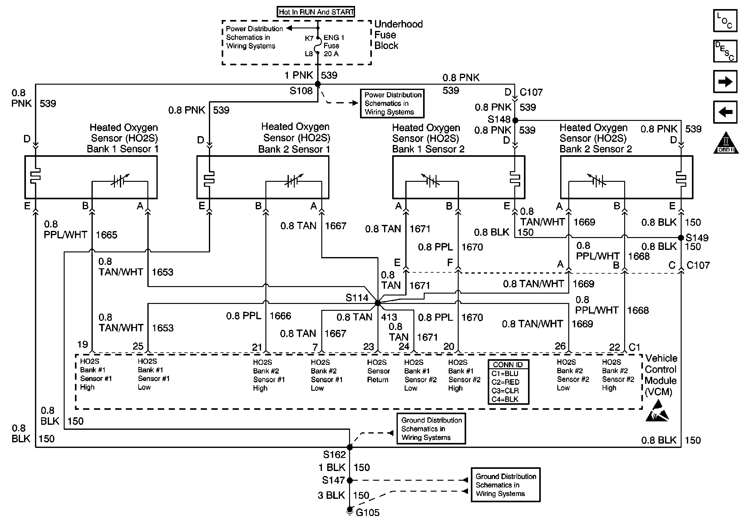
| Figure 10: |
Heated Oxygen Sensors, California Emissions (NB6)
|
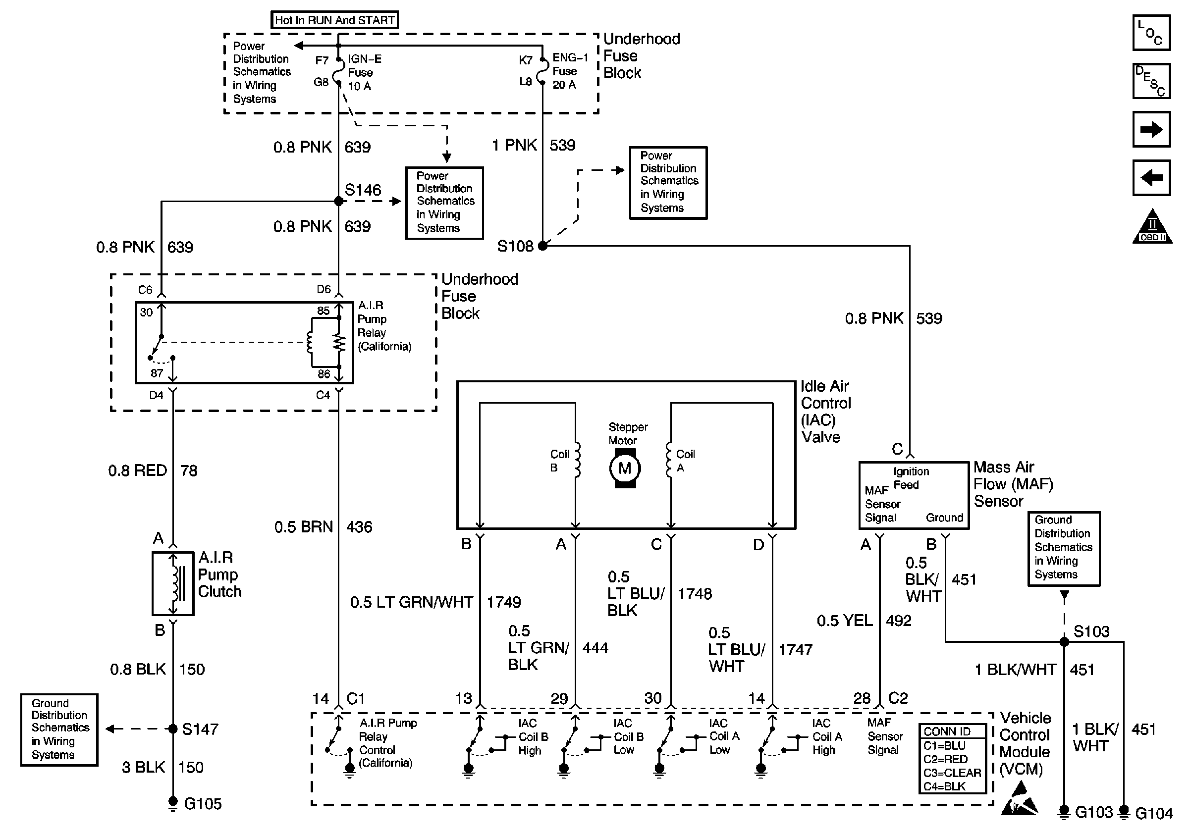
| Figure 11: |
A.I.R., IAC, and MAF Controls
|
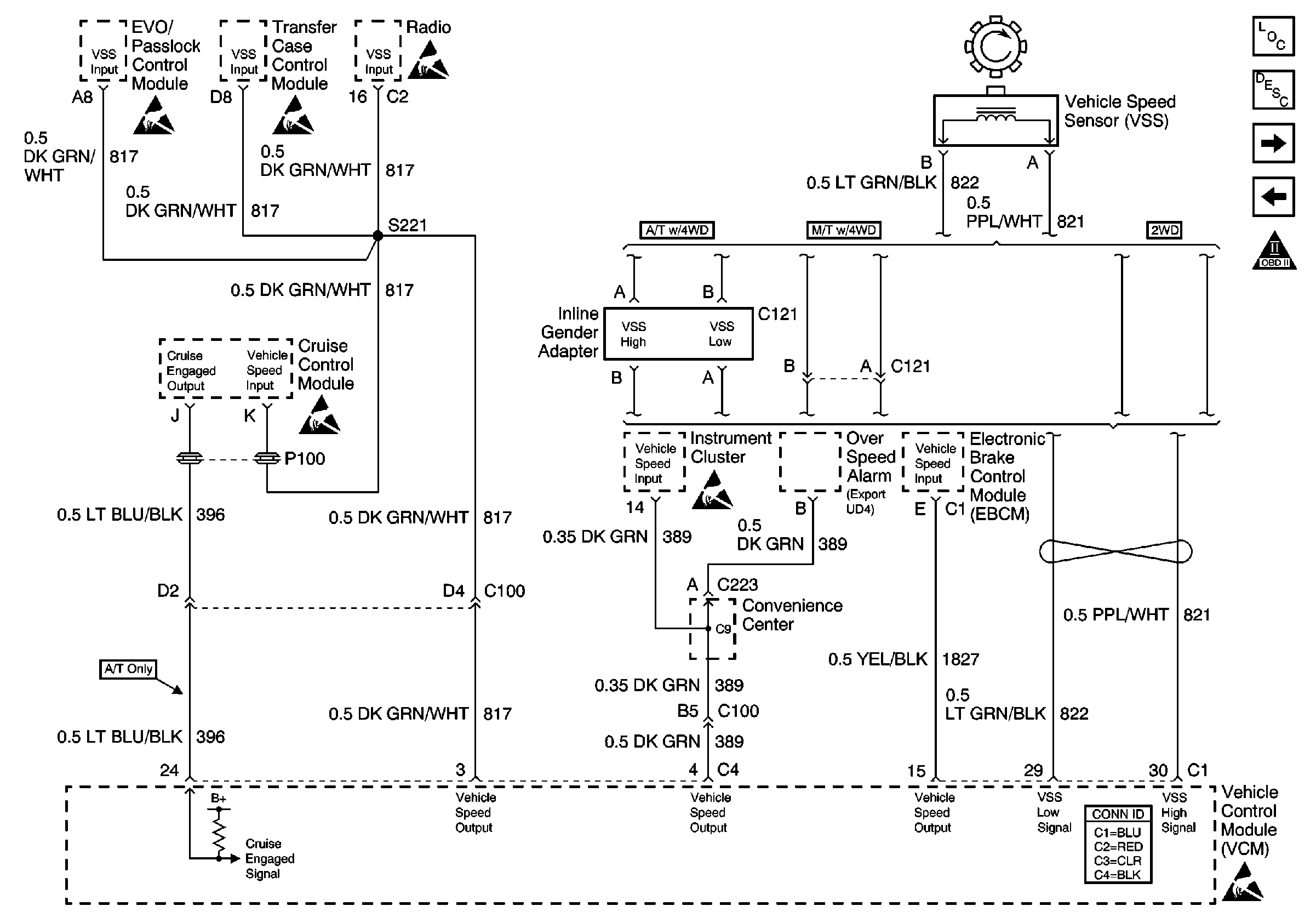
| Figure 12: |
VSS Circuit and Cruise Control
|
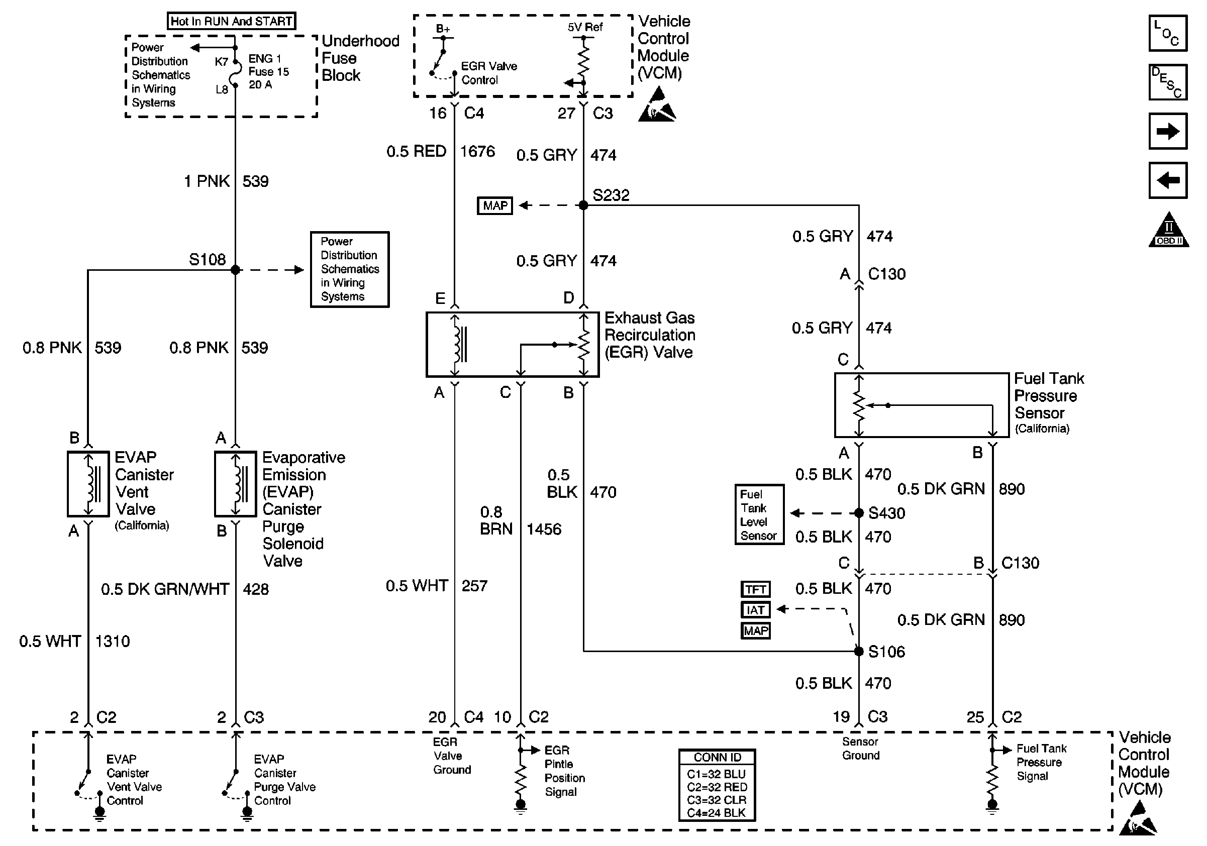
| Figure 13: |
EVAP and EGR Controls, Fuel Tank Pressure Sensor
|
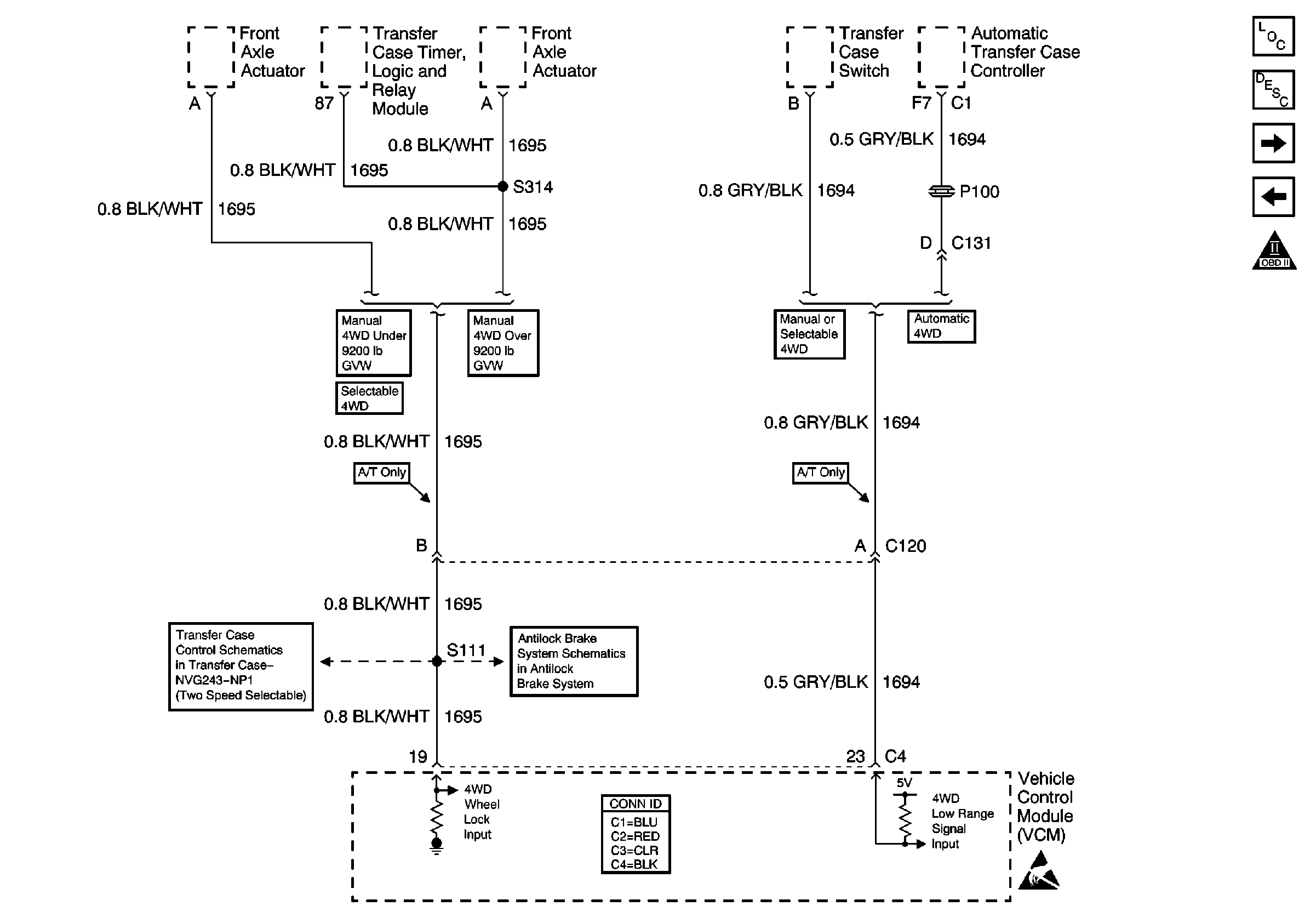
| Figure 14: |
Transfer Case Circuits
|
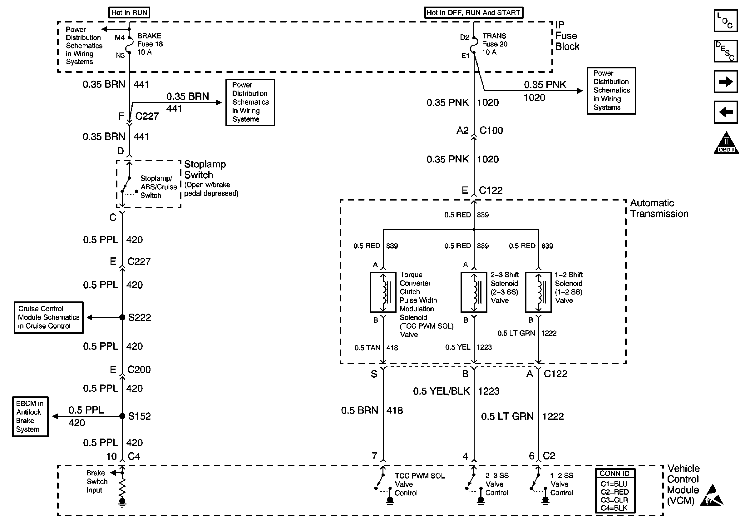
| Figure 15: |
A/T Controls--Shift Solenoids, TCC/Stoplamp Switch
|
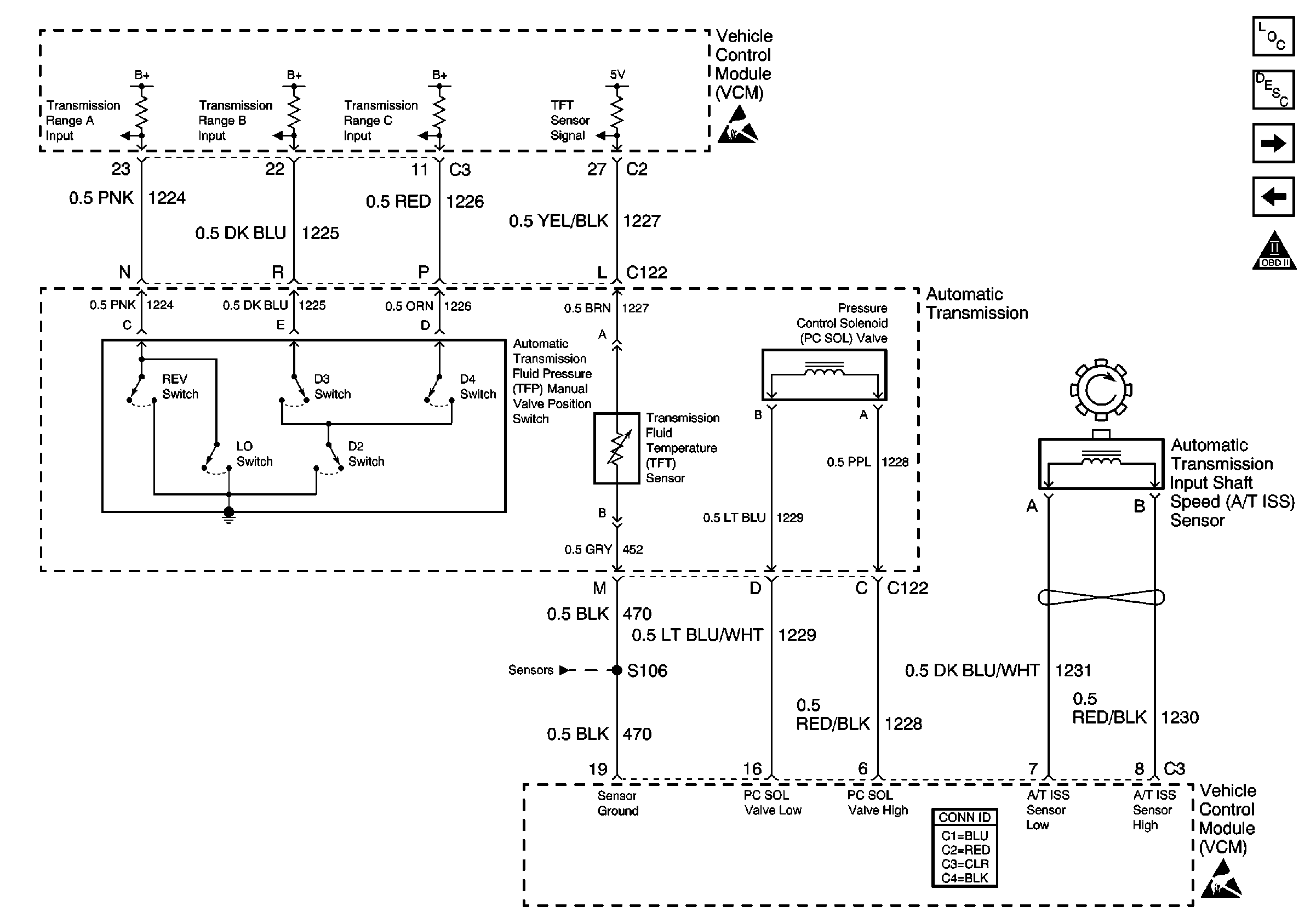
| Figure 16: |
A/T Controls--Internal Switches. TFT, PC Solenoid Valve, and TISS
|
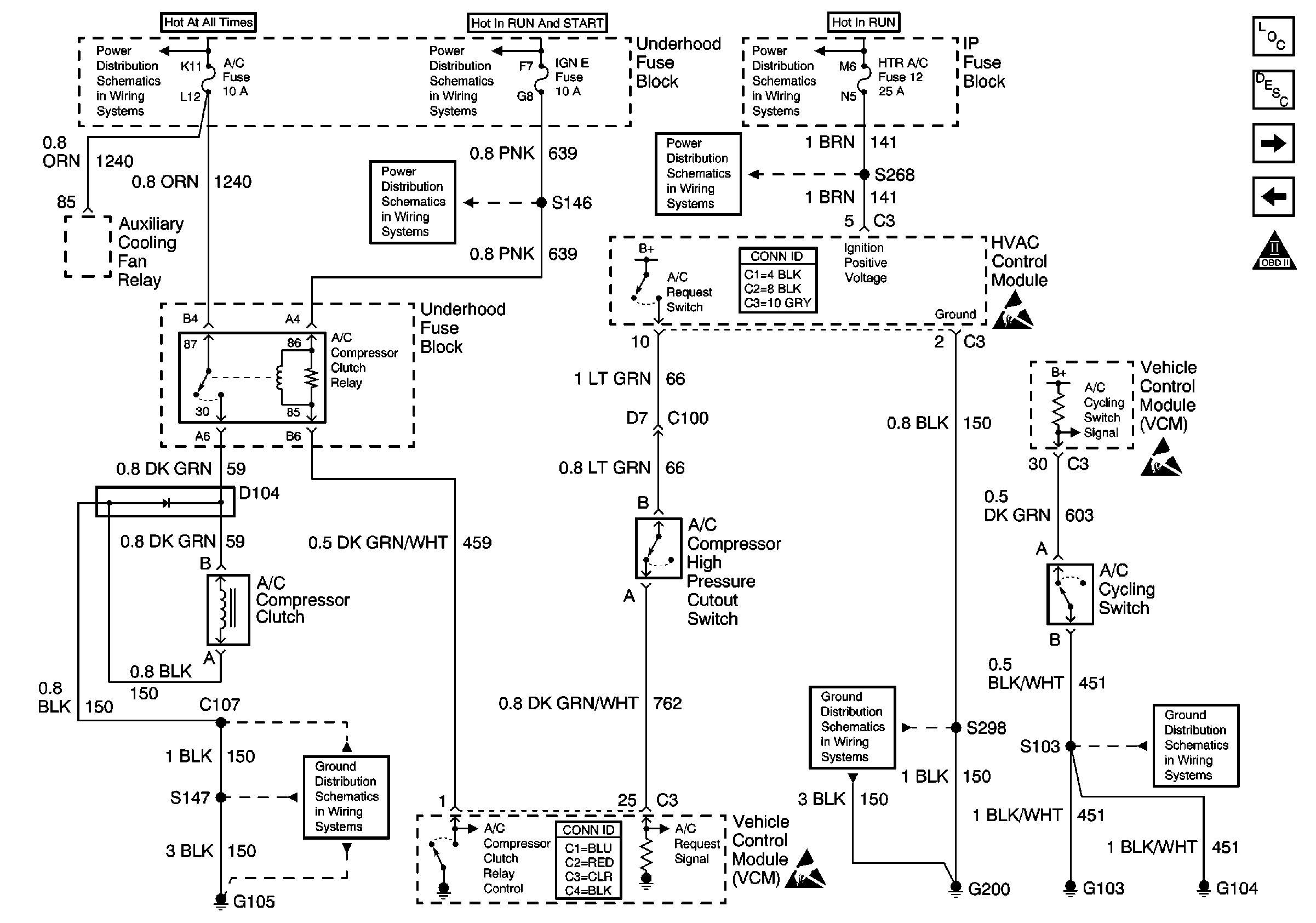
| Figure 17: |
A/C Compressor Control
|
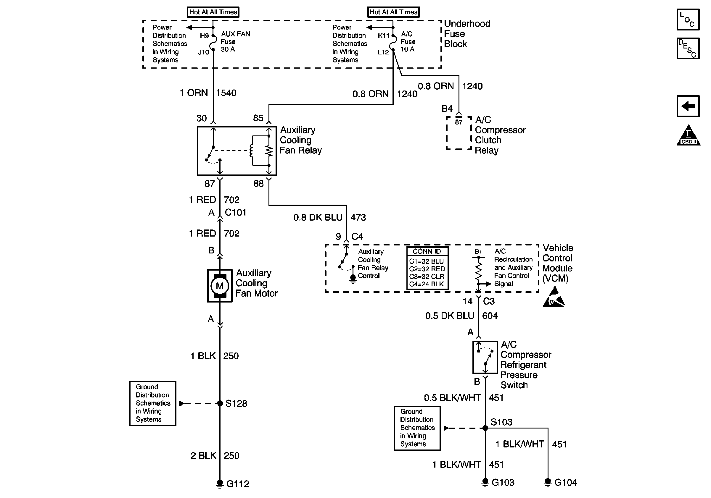
| Figure 18: |
Auxiliary Engine Cooling Fan Control
|


