Steering Column Replacement for Chevrolet Chevy K Silverado - 4WD 1999
Tools Required
J 42640 Steering Column Anti-Rotation Pin

Removal Procedure
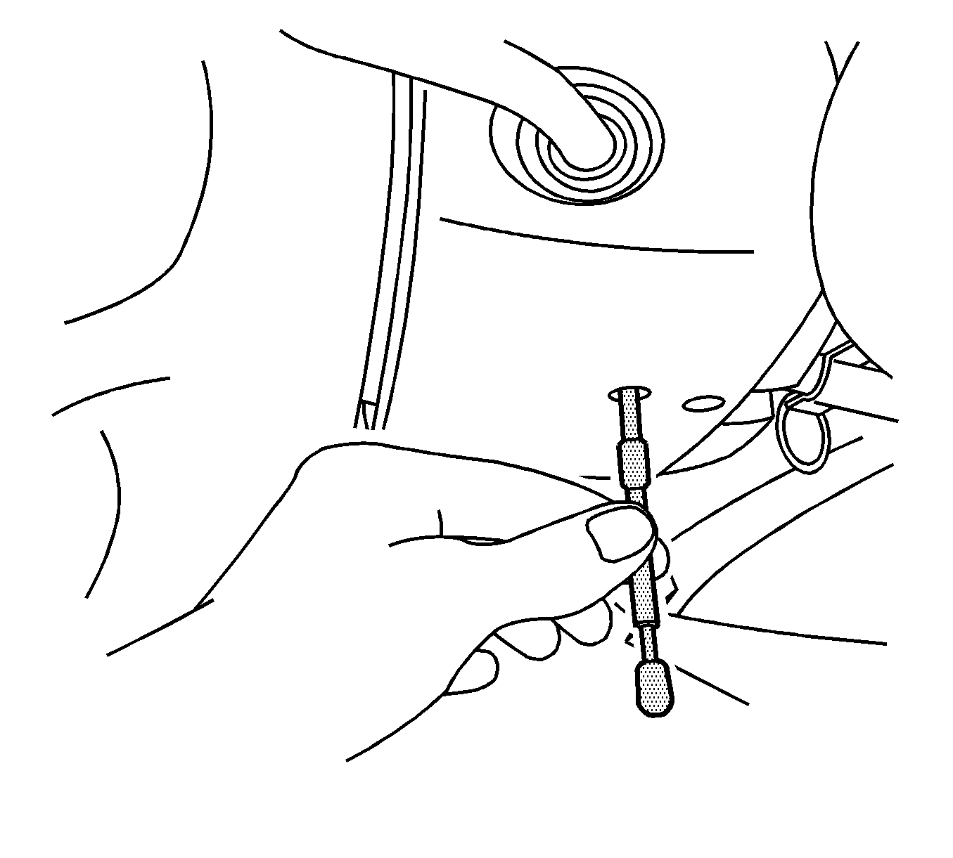
- Install the J 42640 in the steering column lower access hole.
- Set the front wheels in the straight-ahead position.
- Set the steering wheel in the locked position.
- Disconnect the negative battery cable.
- Disable the supplemental inflatable restraint (SIR) system. Refer to Disabling the SIR System in SIR.
- Remove the knee bolster. Refer to Knee Bolster Replacement in Instrument Panel, Gauges and Console.
- Disconnect the transmission control cable from the column.
- Disconnect the steering column harness at the connectors.
- Remove the body control module bracket. Do not disconnect the harness from the body control module. Refer to Body Control Module Replacement in Body Control System.
- Disconnect the SIR connector position assurance (CPA) from the rear of the body control module bracket.
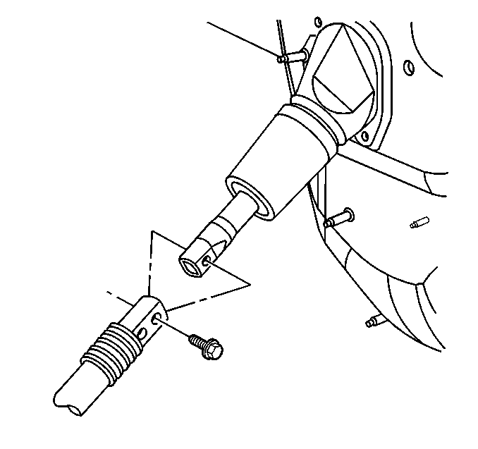
- Remove the bolt from the upper to the lower shaft connection.
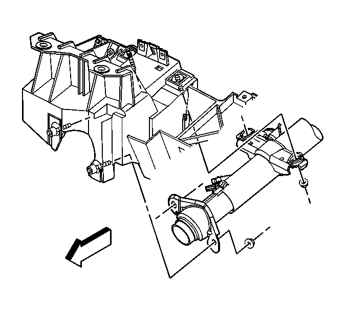
- Remove the nuts from the upper and the lower support brackets.
- Insert J 42640 anti rotation pin in Steering Column.
- Lower the steering column.
- Remove the steering column from the vehicle.
Notice: The wheels of the vehicle must be straight ahead and the steering column in the LOCK position before disconnecting the steering column or intermediate shaft from the steering gear. Failure to do so will cause the SIR coil assembly to become uncentered, which may cause damage to the coil assembly.
Caution: Unless directed otherwise, the ignition and start switch must be in the OFF or LOCK position, and all electrical loads must be OFF before servicing any electrical component. Disconnect the negative battery cable to prevent an electrical spark should a tool or equipment come in contact with an exposed electrical terminal. Failure to follow these precautions may result in personal injury and/or damage to the vehicle or its components.
Important: When the steering column is removed from the vehicle, actions such as a sharp blow on the end of the steering shaft or shift lever, leaning on the column assembly, or dropping the assembly could shear or loosen the plastic fasteners that maintain column rigidity.
Installation Procedure
- Install the steering column to the vehicle.
- Install the nuts to lower support bracket first, then upper brackets.
- Install the bolt to the upper and the lower shaft connection.
- Connect the SIR connector position assurance (CPA). Attach the CPA to the rear of the body control module bracket.
- Install the body control module bracket. Refer to Body Control Module Replacement in Body Control System.
- Connect the steering column harness to the connectors.
- Connect the transmission control cable to the column.
- Install the knee bolster. Refer to Knee Bolster Replacement in Instrument Panel, Gauges, and Console.
- Enable the supplemental inflatable restraint (SIR) system. Refer to Enabling the SIR System in SIR.
- Connect the negative battery cable.
- Remove the J 42640 from the steering column lower access hole.
Notice: Use the correct fastener in the correct location. Replacement fasteners must be the correct part number for that application. Fasteners requiring replacement or fasteners requiring the use of thread locking compound or sealant are identified in the service procedure. Do not use paints, lubricants, or corrosion inhibitors on fasteners or fastener joint surfaces unless specified. These coatings affect fastener torque and joint clamping force and may damage the fastener. Use the correct tightening sequence and specifications when installing fasteners in order to avoid damage to parts and systems.
Tighten
Tighten the nuts to 30 N·m (22 lb ft).
Tighten
Tighten the bolt to 50 N·m (37 lb ft).
Perform the Idle Learn Procedure for 4.8L, 5.3L and 6.0L engines only. Refer to PCM Idle Learn Procedure in Engine Controls-4.8L, 5.3L and 6.0L.
