Product Safety - Front Wheel Speed Sensor Corrosion

| Subject: | 05068C -- FRONT WHEEL SPEED SENSOR CORROSION |
| Models: | 1999-2002 CHEVROLET SILVERADO |
| 2000-2002 CHEVROLET TAHOE, SUBURBAN |
| 2002 CHEVROLET AVALANCHE |
| 1999-2002 GMC SIERRA |
| 2000-2002 GMC YUKON, YUKON XL |
| LOCATED IN THE SEVERE CORROSION AREAS LISTED BELOW |
Some breakpoints in this bulletin have been revised. Additional vehicles that have moved into the severe corrosion areas have been added. Please discard all copies of bulletin 05068B, issued April 2006.
Condition
General Motors has decided that a defect, which relates to motor vehicle safety, exists in certain 1999-2002 Chevrolet Silverado, 2000-2002 Chevrolet Tahoe, Suburban, 2002 Chevrolet Avalanche, 1999-2002 GMC Sierra, 2000-2002 GMC Yukon, Yukon XL vehicles located in the areas listed below. These vehicles may have a condition permitting corrosion to occur between the front hub/bearing assembly and the wheel speed sensor. If the brakes are applied while the vehicle is traveling at a speed of greater than 6 km/h (3.7 mph) but less than 16 km/h (10 mph), the corrosion may cause an unwanted anti-lock brake system (ABS) activation. If this condition occurred where stopping distance is limited, a crash could occur.
| • | Connecticut |
| • | Delaware |
| • | District of Columbia |
| • | Illinois |
| • | Indiana |
| • | Iowa |
| • | Maine |
| • | Maryland |
| • | Massachusetts |
| • | Michigan |
| • | Minnesota |
| • | Missouri |
| • | New Hampshire |
| • | New Jersey |
| • | New York |
| • | Ohio |
| • | Pennsylvania |
| • | Rhode Island |
| • | Vermont |
| • | West Virginia |
| • | Wisconsin |
Correction
Dealers are to inspect, clean, and treat the affected area. In some cases, the front wheel speed sensor may require replacement.
Vehicles Involved
Involved are certain 1999-2002 Chevrolet Silverado, 2000-2002 Chevrolet Tahoe, Suburban, 2002 Chevrolet Avalanche, 1999-2002 GMC Sierra, and 2000-2002 GMC Yukon, Yukon XL vehicles located in severe corrosion areas and built within these VIN breakpoints:
Year | Division | Model | From | Through |
|---|---|---|---|---|
2002 | Chevrolet | Avalanche | 2G100011 | 2G363853 |
1999 | Chevrolet | Silverado | X1100007 | X1299263 |
1999 | Chevrolet | Silverado | XE100013 | XE256726 |
1999 | Chevrolet | Silverado | XZ100014 | XZ214615 |
2000 | Chevrolet | Silverado | Y1100007 | Y1409278 |
2000 | Chevrolet | Silverado | YE100004 | YE433948 |
2000 | Chevrolet | Silverado | YZ100007 | YZ371929 |
2001 | Chevrolet | Silverado | 11100003 | 11408135 |
2001 | Chevrolet | Silverado | 1E100046 | 1E346619 |
2001 | Chevrolet | Silverado | 1F106154 | 1F213776 |
2001 | Chevrolet | Silverado | 1Z100004 | 1Z335173 |
2002 | Chevrolet | Silverado | 21100010 | 21430583 |
2002 | Chevrolet | Silverado | 2E100039 | 2E306055 |
2002 | Chevrolet | Silverado | 2F100022 | 2F249730 |
2002 | Chevrolet | Silverado | 2Z100022 | 2Z348507 |
2000 | Chevrolet | Suburban | YG10006 | YG229688 |
2000 | Chevrolet | Suburban | YJ100096 | YJ209572 |
2001 | Chevrolet | Suburban | 1G100028 | 1G289556 |
2001 | Chevrolet | Suburban | 1J100018 | 1J318221 |
2002 | Chevrolet | Suburban | 2G100306 | 2G363792 |
2002 | Chevrolet | Suburban | 2J100007 | 2J343575 |
2002 | Chevrolet | Suburban | 2R199712 | 2R327763 |
2000 | Chevrolet | Tahoe | YJ100003 | YJ211862 |
2001 | Chevrolet | Tahoe | 1J100047 | 1J318217 |
2001 | Chevrolet | Tahoe | 1R100005 | 1R228102 |
2002 | Chevrolet | Tahoe | 2J100043 | 2J344546 |
2002 | Chevrolet | Tahoe | 2R109204 | 2R330531 |
1999 | GMC | Sierra | X1500002 | X1571274 |
1999 | GMC | Sierra | XE500010 | XE851658 |
1999 | GMC | Sierra | XZ500014 | XZ540991 |
2000 | GMC | Sierra | Y1100005 | Y1409250 |
2000 | GMC | Sierra | YE100026 | YE901599 |
2000 | GMC | Sierra | YZ100024 | YZ370502 |
2001 | GMC | Sierra | 11100009 | 11408106 |
2001 | GMC | Sierra | 1E100007 | 1E901430 |
2001 | GMC | Sierra | 1F106149 | 1F213708 |
2001 | GMC | Sierra | 1Z100045 | 1Z335202 |
2002 | GMC | Sierra | 21100003 | 21430563 |
2002 | GMC | Sierra | 2E100007 | 2E306397 |
2002 | GMC | Sierra | 2F100008 | 2F247747 |
2002 | GMC | Sierra | 2Z100013 | 2Z900932 |
2000 | GMC | Yukon | YJ100002 | YJ211863 |
2001 | GMC | Yukon | 1J100012 | 1J314635 |
2001 | GMC | Yukon | 1R100092 | 1R228070 |
2002 | GMC | Yukon | 2J100012 | 2J344554 |
2002 | GMC | Yukon | 2R113694 | 2R330419 |
2000 | GMC | Yukon XL | YG100014 | YG229685 |
2000 | GMC | Yukon XL | YJ100172 | YJ211810 |
2001 | GMC | Yukon XL | 1G100018 | 1G289600 |
2001 | GMC | Yukon XL | 1J100013 | 1J318175 |
2002 | GMC | Yukon XL | 2G100132 | 2G363800 |
2002 | GMC | Yukon XL | 2J100058 | 2J343335 |
2002 | GMC | Yukon XL | 2R225724 | 2R319698 |
Important: Dealers retailers should confirm vehicle eligibility through GMVIS (GM Vehicle Inquiry System) prior to beginning recall repairs. [Not all vehicles within the above breakpoints may be involved.]
For dealers with involved vehicles, a Campaign Initiation Detail Report (CIDR) containing the complete vehicle identification number, customer name and address data has been prepared and will be loaded to the GM DealerWorld (US) Recall Information. Dealers will not have a report available if they have no involved vehicles currently assigned.
The Campaign Initiation Detail Report may contain customer names and addresses obtained from Motor Vehicle Registration Records. The use of such motor vehicle registration data for any purpose other than follow-up necessary to complete this recall is a violation of law in several states/provinces/countries. Accordingly, you are urged to limit the use of this report to the follow-up necessary to complete this recall.
Parts Information
Parts required to complete this recall are to be obtained from General Motors Service Parts Operations (GMSPO). Please refer to your "involved vehicles listing" before ordering parts. Normal orders should be placed on a DRO = Daily Replenishment Order. In an emergency situation, parts should be ordered on a CSO = Customer Special Order.
Note: Very few vehicles will require front wheel speed sensor replacement; if required, order appropriate part from GMSPO.
Part Number | Description | Qty |
|---|---|---|
89022217 | Lubricant, Rust Penetrating (will service 50+ vehicles) | 1 |
01051344 | Lubricant, Wheel Bearing (will service 25+ vehicles) | 1 |
Service Procedure
The following procedure provides instructions for repairing a corrosion condition where the front wheel speed sensor mounts on the front wheel bearing assembly.
- Raise the vehicle on a suitable hoist and support as necessary.
- Remove both front tires and wheels.
- Compress the front brake caliper pistons.
- Remove the two bolts that attach the front brake caliper mounting brackets to the knuckle.
- Remove the brake caliper and bracket as an assembly and support it with heavy mechanic’s wire or equivalent. DO NOT disconnect the hydraulic brake flexible hose from the caliper.
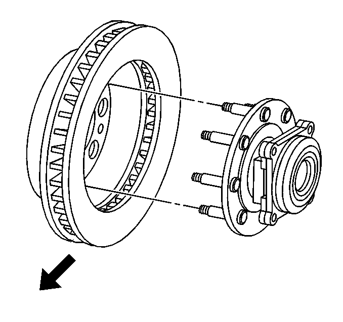
- Mark the relationship of the rotor to the bearing hub.
- If equipped, remove the rotor retaining push nuts from the wheel studs
- Remove the rotor.
- Remove the bolt (1) that attaches the wheel speed sensor to the bearing hub.
- Remove the wheel speed sensor from the bearing hub assembly.
- Inspect to see if the mounting surface on the sensor is flat. Check the mounting surface on the sensor head for flatness by placing it on the edge of a metal machinist’s scale or other suitable straight edge to measure the flatness. Check the sensor for flatness in multiple positions/directions (minimum 3).
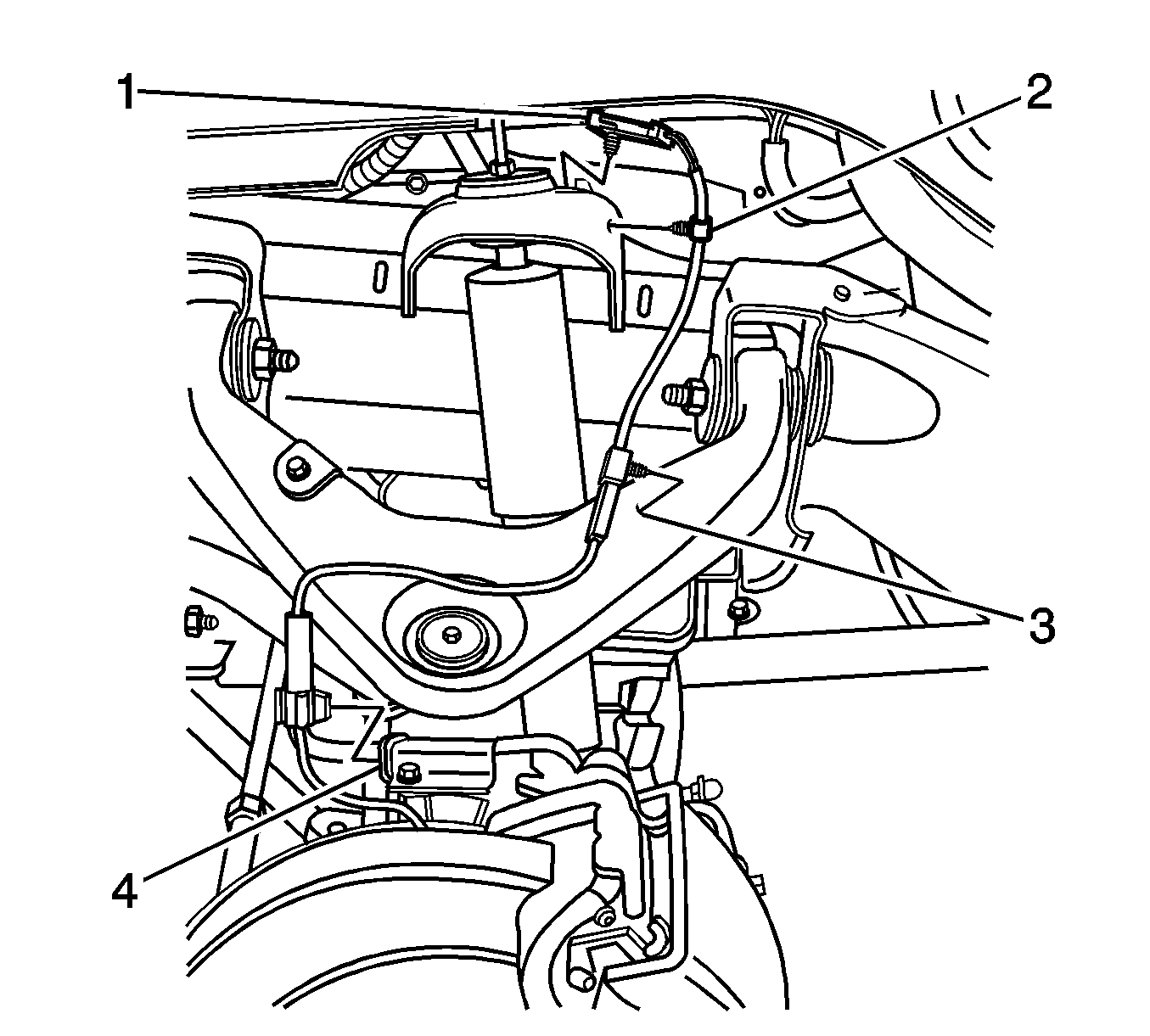
- Remove the wheel speed harness mounting clips from the knuckle (4) upper control arm (3) and frame (2).
- Disconnect the wheel speed harness electrical connector (1) from the vehicle wiring harness.
- Connect the new wheel speed sensor harness electrical connector to the vehicle wiring harness.
- Attach the wheel speed sensor harness to the frame, upper control arm, and the knuckle.
- Temporarily plug the wheel speed sensor hole (1) in the bearing hub to prevent debris from entering it when you clean it.
- Using a wire brush, sandpaper, emery cloth, scotch brite, or equivalent, thoroughly clean the wheel speed sensor mounting surface (2) on the bearing hub to remove any rust or corrosion.
- Using compressed air, remove all debris from the bearing hub surface.
- Using a clean shop towel, clean the sensor and the O-ring.
- Apply (spray) two thin coats of the specified rust penetrating lubricant (corrosion inhibitor) listed in this bulletin, to the complete sensor mounting surface on the bearing hub. Allow to dry for 3-5 minutes between coats.
- When the corrosion inhibitor is dry to the touch (about 10 minutes), apply a light coating of the specified grease to the complete sensor mounting surface on the bearing hub and to the sensor and O-ring.
- Remove the temporary plug from the hole in the bearing hub.
- Install the wheel speed sensor in the bearing hub and install the bolt. Ensure that the sensor is seated flat against the hub.
- Disconnect the front wheel speed sensor connector and place a digital volt meter (DVM) across the terminals of the wheel speed sensor connector. Rotate the bearing at approximately one revolution per second. The minimum reading should be at least 350 ACmV’s. If the reading is less than 350 ACmV’s, the wheel speed sensor must be replaced. Follow Steps 12-15 for instructions on replacing the wheel speed sensor. This step must be repeated after the new sensor has been installed.
- Align the rotor to its original position on the hub and install the rotor.
- Install the caliper and caliper mounting bracket assembly.
- Perform the following procedure before installing the brake caliper bracket mounting bolts.
- Install the caliper bracket mounting bolts. Tighten the brake caliper mounting bracket mounting bolts to the specification listed below.
- Install the front tire and wheel assembly.
- Complete Steps 21-30 on the opposite side front wheel speed sensor.
- Lower the vehicle.
- With the engine OFF, gradually apply the brake pedal to approximately 2/3 of its travel distance.
- Slowly release the brake pedal.
- Wait 15 seconds and repeat Steps 32-33 until a firm pedal is obtained. This will properly seat the brake caliper pistons and brake pads.
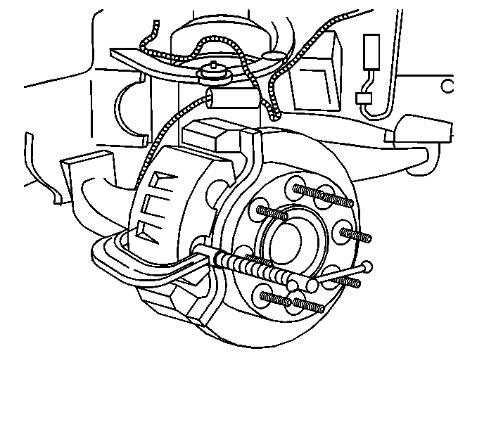
| 3.1. | Install a large C-clamp over the top of the caliper housing and against the back of the outboard pad. |
| 3.2. | Slowly tighten the C-clamp until the pistons are pushed completely into the caliper bores. |
| 3.3. | Remove the C-clamp from the caliper. |
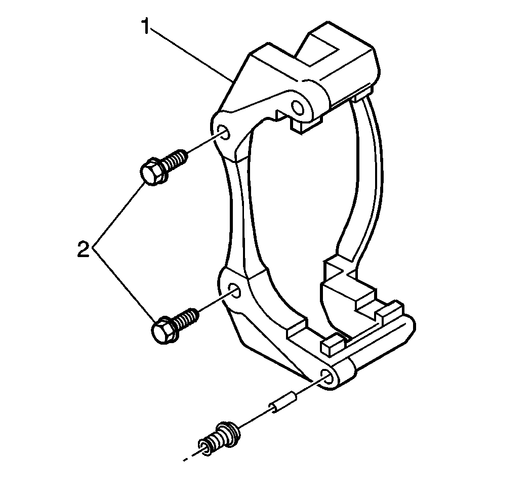
Important: It is not necessary to remove the front brake caliper from the bracket when removing the bracket in the next step.
Notice: Support the brake caliper with heavy mechanic’s wire, or equivalent, whenever it is separated from its mount, and the hydraulic flexible brake hose is still connected. Failure to support the caliper in this manner will cause the flexible brake hose to bear the weight of the caliper, which may cause damage to the brake hose and in turn may cause a brake fluid leak.
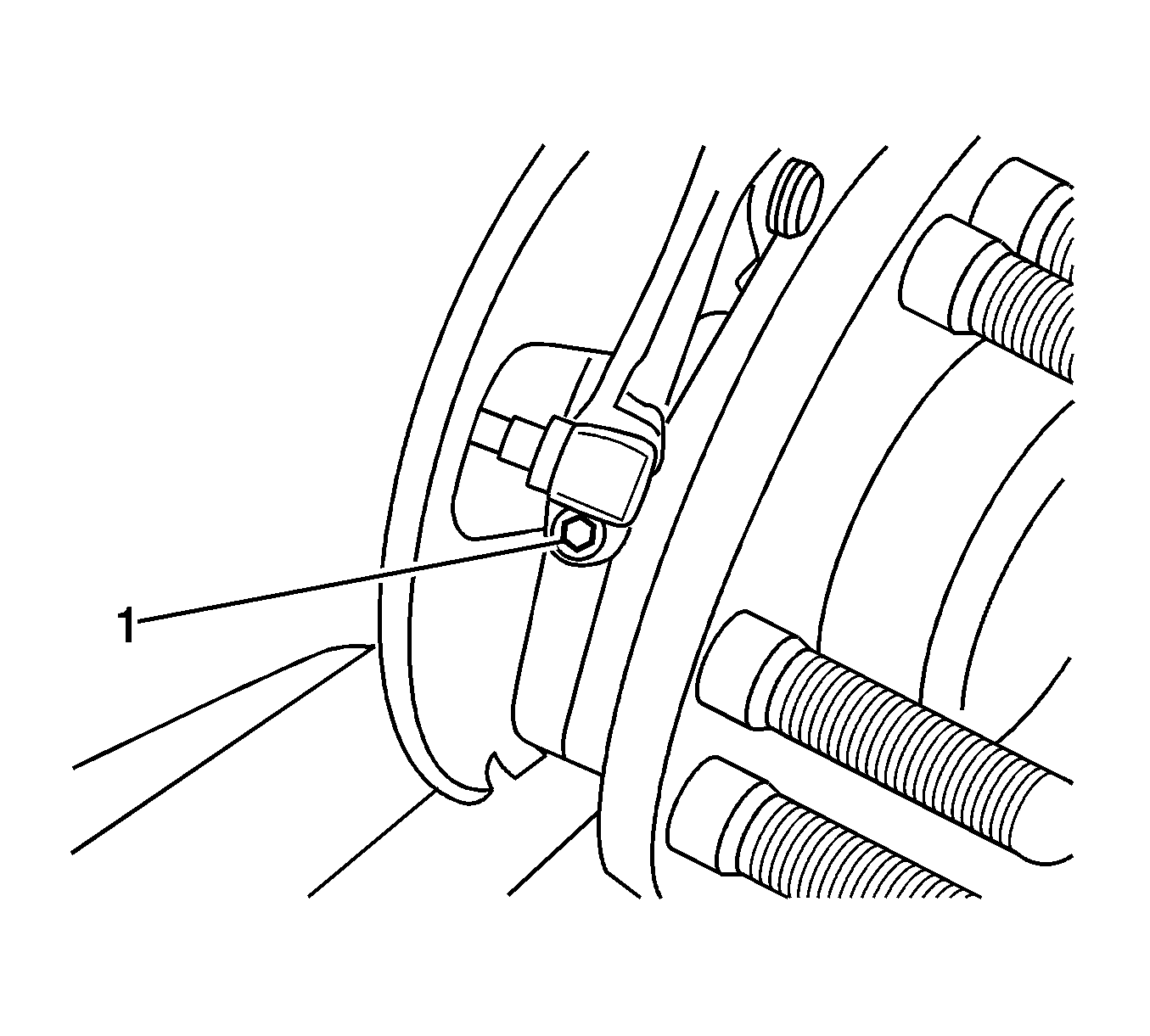
Notice: Carefully remove the sensor by pulling it straight out of the bore. DO NOT use a screwdriver or other device to try to pry the sensor out of the bore. Prying will cause the sensor body to break off in the bore.
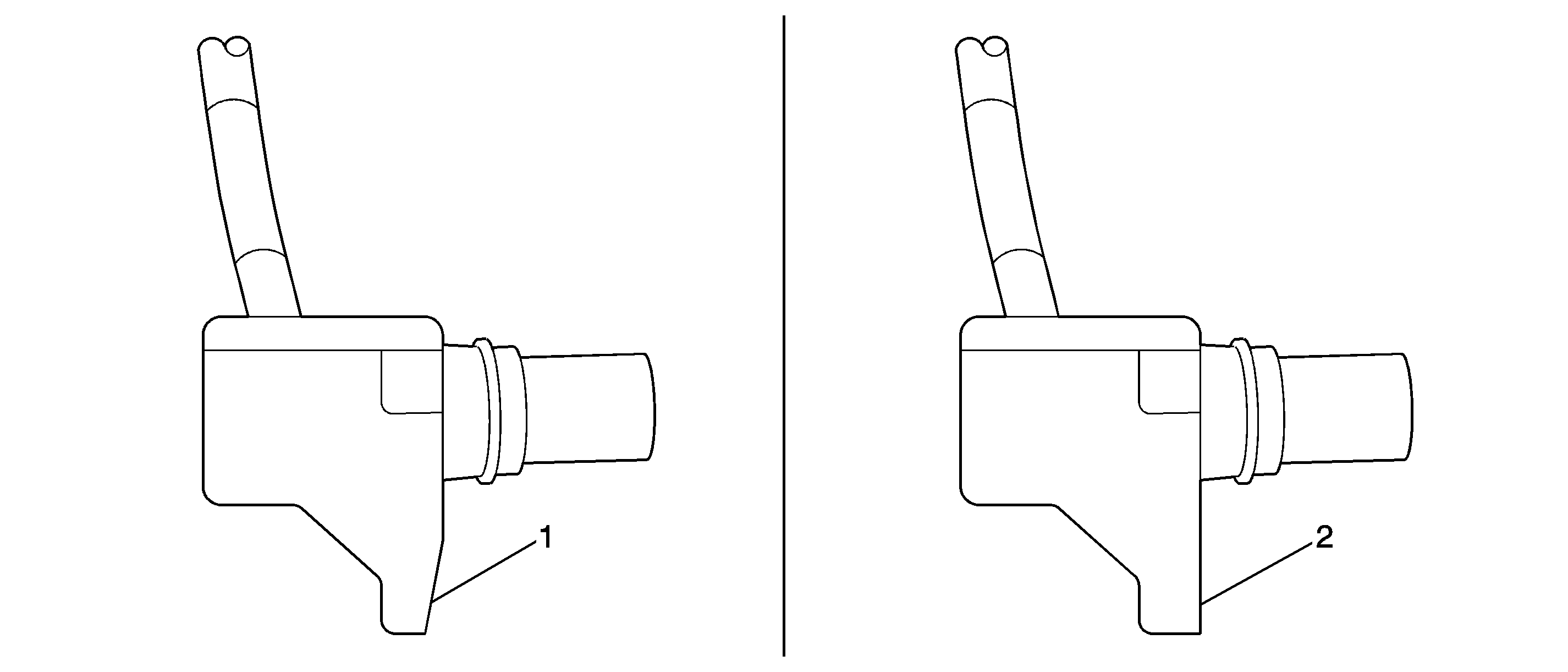
Important: The mounting surface on the sensor must be flat in the next step in order to be mounted correctly on the bearing hub assembly. If the mounting surface on the sensor is warped or bent, the sensor must be replaced.
| • | If the sensor mounting surface is NOT flat (1), the sensor must be replaced. Proceed to the next step and replace the sensor. |
| • | If the sensor mounting surface IS flat (2), the sensor IS to be reused. Proceed to Step 16. |
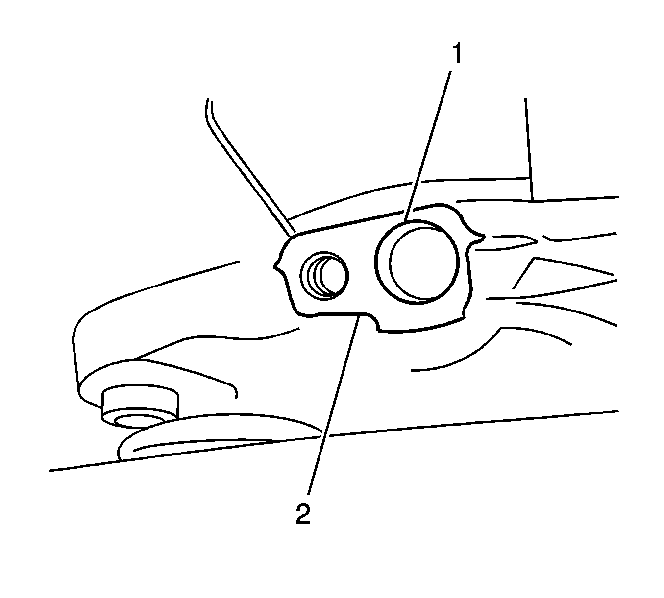
Important: All rust and corrosion must be removed from the wheel speed sensor mounting surfaces on the bearing hub in the next step.
Important: While the corrosion inhibitor is drying in the next step, begin performing Steps 3-20 on the opposite side front wheel speed sensor.
Tighten
Tighten the wheel speed sensor mounting bolt to 18 N·m(13 lb ft).
Notice: Whenever the brake rotor has been separated from the wheel bearing flange, clean any rust or foreign material from the mating surface of the rotor and flange. Failure to do this may result in increased lateral runout of the rotor and brake.
Important: If the rotor was removed using the jack screw method, you must ensure that the hub flange is free of nicks or marks caused by this procedure. Remove all raised nicks or marks before installing the rotor.
| 27.1. | Remove all traces of the original adhesive patch. |
| 27.2. | Clean the threads of the bolt with brake parts cleaner, or the equivalent, and allow to dry. |
| 27.3. | Apply threadlocker to the threads of the bolts. |
Tighten
| • | 1500 Series vehicles - 175 N·m(129 lb ft) |
| • | 2500 Series vehicles - 300 N·m(221 lb ft) |
Tighten
Tighten the wheel nuts to 190 N·m(140 lb ft).
Customer Reimbursement
All customer requests for reimbursement for previous repairs for the recall condition will be handled by the Customer Assistance Center, not by dealers.
A General Motors Customer Reimbursement Procedure and Claim Form is included with the customer letter.
Important: (For GM US Only) Refer to the GM Service Policies and Procedures Manual, section 6.1.12, for specific procedures regarding customer reimbursement and the form.
Claim Information
Submit a Product Recall Claim with the information indicated below:
Repair Performed | Part Count | Part No. | Parts Allow | CC-FC | Labor Op | Labor Hours | Net Item |
|---|---|---|---|---|---|---|---|
Inspect Wheel Speed Sensor (inc. cleaning) | 0 | N/A | N/A | MA-96 | V1410 | 0.8 | ** |
Add: Vehicles With 8-Lug Nut Wheels | 0.1 | ||||||
Inspect & Replace One or Both Wheel Speed Sensor(s) (inc. cleaning) | 1-2 | -- | * | MA-96 | V1411 | 0.9 | ** |
Add: Vehicles With 8-Lug Nut Wheels | 0.1 | ||||||
Customer Reimbursement (CAC) (Repair will still need to be performed) | N/A | N/A | N/A | MA-96 | V1412 | 0.2 | *** |
* The "Parts Allowance" should be the sum total of the current GMSPO Dealer net price plus applicable Mark-Up for the front wheel speed sensor needed to complete the repair. ** The amount identified in the "Net Item" column should represent the actual sum total of the current GMSPO Dealer net price plus applicable Mark-Up for the actual amount of lubricants needed to perform the required repairs, not to exceed $0.75. *** The amount identified in the "Net Item" column should represent the dollar amount reimbursed to the customer. | |||||||
Refer to the General Motors WINS Claims Processing Manual for details on Product Recall Claim Submission.
Customer Notification
General Motors will notify customers of this recall on their vehicle (see copy of customer letter included with this bulletin).
Dealer Recall Responsibility
The US National Traffic and Motor Vehicle Safety Act provides that each vehicle that is subject to a recall of this type must be adequately repaired within a reasonable time after the customer has tendered it for repair. A failure to repair within sixty days after tender of a vehicle is prima facie evidence of failure to repair within a reasonable time. If the condition is not adequately repaired within a reasonable time, the customer may be entitled to an identical or reasonably equivalent vehicle at no charge or to a refund of the purchase price less a reasonable allowance for depreciation. To avoid having to provide these burdensome remedies, every effort must be made to promptly schedule an appointment with each customer and to repair their vehicle as soon as possible. In the recall notification letters, customers are told how to contact the US National Highway Traffic Safety Administration if the recall is not completed within a reasonable time.
All unsold new vehicles in dealers' possession and subject to this recall must be held and inspected/repaired per the service procedure of this recall bulletin before customers take possession of these vehicles.
Dealers are to service all vehicles subject to this recall at no charge to customers, regardless of mileage, age of vehicle, or ownership, from this time forward.
Customers who have recently purchased vehicles sold from your vehicle inventory, and for which there is no customer information indicated on the dealer listing, are to be contacted by the dealer. Arrangements are to be made to make the required correction according to the instructions contained in this bulletin. A copy of the customer letter is provided in this bulletin for your use in contacting customers. Recall follow-up cards should not be used for this purpose, since the customer may not as yet have received the notification letter.
In summary, whenever a vehicle subject to this recall enters your vehicle inventory, or is in your dealership for service in the future, you must take the steps necessary to be sure the recall correction has been made before selling or releasing the vehicle.
Dear General Motors Customer:
This notice is sent to you in accordance with the requirements of the National Traffic and Motor Vehicle Safety Act.
Reason For This Recall
General Motors has decided that a defect, which relates to motor vehicle safety, exists in certain 1999-2002 Chevrolet Silverado, 2000-2002 Chevrolet Tahoe, Suburban, 2002 Chevrolet Avalanche, 1999-2002 GMC Sierra, and 2000-2002 GMC Yukon, Yukon XL vehicles located in severe corrosion areas. These vehicles may have a condition permitting corrosion to occur between the front hub/bearing assembly and the wheel speed sensor. If the brakes are applied while the vehicle is traveling at a speed of greater than 3 mph but less than 10 mph, the corrosion may cause an unwanted anti-lock brake system (ABS) activation. If this condition occurred where stopping distance is limited, a crash could occur.
What Will Be Done
Your GM dealer will inspect, clean, and treat the affected area. In some cases, the front wheel speed sensor may require replacement. This service will be performed for you at no charge .
How Long Will The Repair Take?
This service correction will take approximately 1 hour. However, due to service scheduling requirements, your dealer may need your vehicle for a longer period of time.
Contacting Your Dealer
To limit any possible inconvenience, we recommend that you contact your dealer as soon as possible to schedule an appointment for this repair. Should your dealer be unable to schedule a service date within a reasonable time, you should contact the appropriate Customer Assistance Center at the listed number below. The Customer Assistance Center’s hours of operation are from 8:00 AM to 11:00 PM, EST, Monday through Friday.
Division | Number | Text Telephones (TTY) |
|---|---|---|
Chevrolet | 1-800-630-2438 | 1-800-833-2438 |
GMC | 1-866-996-9463 | 1-800-462-8583 |
If, after contacting the appropriate Customer Assistance Center, you are still not satisfied that we have done our best to remedy this condition without charge and within a reasonable time, you may wish to write the Administrator, National Highway Traffic Safety Administration, 400 Seventh Street, SW, Washington, DC 40990; or call the toll-free Vehicle Safety Hotline at 1 888-327-4236 (TTY: 1-800-424-9153); or go to http://www.safercar.gov.
Customer Reply Form
The enclosed customer reply form identifies your vehicle. Presentation of this form to your dealer will assist in making the necessary correction in the shortest possible time. If you no longer own this vehicle, please let us know by completing the form and mailing it back to us.
Reimbursement
The enclosed form explains what reimbursement is available and how to request reimbursement if you have paid for repairs for the recall condition.
Recall Information Online
More information about this recall, including answers to frequently asked questions, can be found at the Owner Center at My GMLink. This free online service offers vehicle and ownership related information along with tools tailored to your specific vehicle. To join, visit www.gm.com/recall and enter your vehicle’s 17-character vehicle identification number (VIN), shown on the enclosed customer reply form.
Federal regulation requires that any vehicle lessor receiving this recall notice must forward a copy of this notice to the lessee within ten days.
We are sorry to cause you this inconvenience; however, we have taken this action in the interest of your safety and continued satisfaction with our products.
General Motors Corporation
Enclosure
05068
